

- Resistor Definition: A resistor is defined as a two-terminal passive electrical element that provides electrical resistance to current flow.
- Primary Function: Resistors limit and regulate current flow in electrical and electronic circuits.
- Measurement Unit: Resistance is measured in Ohms (Ω), which can be converted to milliohms, kiloohms, and megaohms.
- Circuit Connections: Resistors can be connected in series or parallel, affecting the overall resistance differently.
- Resistor Diagram: The circuit symbols for resistors include a zig-zag line (North America) and a small rectangle (Europe and Asia).
What is an Electrical Resistor?
A resistor is a two-terminal passive electrical element that inserts a set electrical resistance into a circuit. Resistance is the opposition to current. A larger ohm value lets less current flow for the same voltage. Catalogue types of resistors include the thermistor and many fixed parts.
Its job in a circuit is to oppose electric current and drop voltage. Circuit diagrams use conventional current. In metals the carriers are electrons, moving the other way.
A resistor is passive: it cannot generate electrical energy. Current through it dissipates power as heat (Joule heating, P = I²R).
Resistors limit current and create voltage drops. Stock values run from milliohms to many megohms.
For an ohmic resistor at a fixed temperature, ohm’s law is V = IR. Voltage across the part is proportional to current through it, and R is that ratio.
What Does a Resistor do?
Uses include current limiting, voltage division, signal-level setting and bias of active devices.
One common case is a single series resistor that limits current through a light-emitting diode (LED). More cases follow.
Protect Against Voltage Spikes
An RC snubber circuit places a resistor and capacitor in series, then that pair across a thyristor. The network limits the rate of voltage rise so the device is not forced on by a high  .
.
The same series resistor also keeps LED current inside the datasheet limit. LEDs fail from excess current, not from voltage alone.
Provide Proper Voltage By Creating Voltage Drop
A series dropper or a divider can set the voltage that a load sees. A switch does not need a dropper to “work”; it is either open or closed.
What is Electrical Resistance Measured in (Resistor Units)?
The SI unit of resistance is the ohm (Ω), named for Georg Simon Ohm. A resistor is specified in ohms: the same unit as the property R.
One ohm is one volt per ampere:
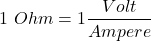
Resistance is also written as V/A. The stored identity 1 Ω = 1 V/A is unchanged.
Preferred prefixes cover that span: milliohm (1 mΩ = 10-3 Ω), kiloohm (1 kΩ = 103 Ω) and megaohm (1 MΩ = 106 Ω).
Electrical Resistor Circuit Symbol
Two resistor symbols are in use. The zigzag is IEEE/ANSI practice, common in North America.
IEC 60617 uses a rectangle. That rectangle is the usual symbol in much of Europe and Asia.
Both symbols are shown below.

Series and Parallel Resistors
Resistors in Series Formula
The circuit below shows n resistors in series.

For series-connected resistors, equivalent resistance is the sum of the individual resistances.
In equation form:

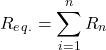
The same current flows through every resistor in a series string.
Example
Three series resistors are 5 Ω, 10 Ω and 15 Ω. Find the equivalent resistance.

Solution:
Given Data:  and
and 
According to formula,


The series equivalent is 30 Ω.
(The figure marks 25 Ω. That label is wrong. 5 + 10 + 15 = 30 Ω.)
Resistors in Parallel Formula
The circuit below shows n resistors in parallel.

For parallel-connected resistors, 1/Req equals the sum of the reciprocals of the branch resistances.
In equation form:

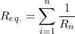
The same voltage appears across every resistor in a parallel group. Voltage does not “flow.”
Example
Three parallel resistors are 10 Ω, 20 Ω and 30 Ω. Find the equivalent resistance.

Solution:
Given Data:  and
and 
According to the formula for parallel resistance,
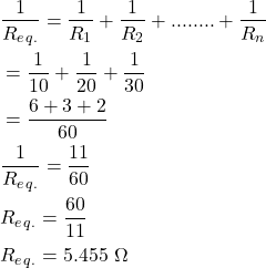

The parallel equivalent is 5.455 Ω (10∥20∥30 = 60/11 Ω).
Resistor Circuits (Example Applications)
LED Current Limiting Resistor
An LED needs its forward current held at or below the datasheet rating. A series resistor is the usual cheap way to do that.
Connect the limiter in series with the LED, as in the figure below.

Calculate the Necessary Value of Current Limiting Resistor
You need three numbers for the resistor:
- LED forward voltage (from datasheet)
- LED maximum forward current (from datasheet)
- VS = supply voltage
Forward voltage VF is the drop when the LED is on, often about 1.8 V (red) to 3.3 V (blue/white) for small indicators. Continuous IF is often 20 mA for 5 mm parts; use the datasheet.
The resistor is then
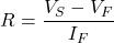
Where,  = Supply Voltage
 = Forward Voltage
 = maximum forward current
Worked numbers:
Example
The figure uses a 3.8 V battery, VF = 3.1 V and IF = 30 mA. Find the series resistor. (30 mA is high for a small indicator; the arithmetic still uses 0.03 A as stored.)

Solution:
Given Data:  ,
,  ,
, 
Substitute into the equation:
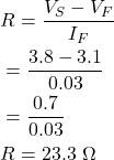
R = (3.8 − 3.1) / 0.03 = 23.3 Ω. Pick the next standard value above that, and check wattage (I²R ≈ 21 mW here).
Pull-up Resistors
A pull-up resistor holds a logic node at a defined high when nothing else drives it.
With no other driver, the node sits high through the resistor. A pull-down does the same job to logic low, toward ground.
Open inputs on ICs, microcontrollers and digital logic gates float unless biased. A pull-up (or the chip’s internal pull-up) sets a known level.
A typical use is a switch or transistors that connect a node to ground, while the resistor ties that node to VCC. The figure below is that arrangement.

With the switch closed, Vin at the gate is at ground. With the switch open, Vin is pulled to the high rail shown as Vin in the figure (the pull-up supply).
When the switch is open the resistor biases the pin. With no pull-up the pin floats (high impedance) and can read randomly.
4.7 kΩ is a common pull-up. The value is a trade-off between speed, power and noise; 1 kΩ to 100 kΩ is a usual band.
Voltage Drop Across a Resistor
The voltage drop across a resistor is the potential difference between its two ends. In DC circuits it is also called the IR drop.
Ohm’s law gives that drop: V = IR for an ohmic part.

In symbols:

Sign for IR Drops (Voltage Drops)
The sign of that drop follows the assumed current direction (passive sign convention).
Take current I through R from A toward B, as in the figure.
A is then at the higher potential. Walking A to B is a fall of IR (often written −IR in KVL). Walking B to A is a rise +IR.
Reverse the assumed current and the signed drop reverses.
Resistor Color Codes
Axial through-hole resistors often use coloured bands for value and tolerance. Surface-mount parts usually print digits instead.
A four-band part has three bands grouped, then a gap, then the tolerance band.

From the left (away from the tolerance band): two digits, then the multiplier, then tolerance. Five-band codes add a third digit.

The table below is the usual 4-band colour map.

Notes:
- The Gold and Silver band is always placed to the right.
- The resistor value is always read from left to right.
- If there is no tolerance band, find the side with a band near to a lead and make that the first band.
Example (How to Calculate Resistor Value?)
Read green, blue, red, gold. Find value and tolerance.

Solution:
From the colour table:
| Green | Blue | Red | Golden |
| 5 | 6 | 102 |  |

Thus, the value of resistance is  with tolerance.
The allowed band is


Hence, the value of resistance is in between  and
and  .
.
Character or Letter Coding (RKM Code)
Tiny parts often use letter marking (RKM / BS 1852 style) instead of colour bands.
R stands in for the decimal in ohms, K in kilohms, M in megohms. 4K7 is 4.7 kΩ. Examples:
| Resistance | Letter Code |
| 0.3 Ω | R3 |
| 0.47 Ω | R47 |
| 1 Ω | 1R0 |
| 1 KΩ | 1K |
| 4.7 KΩ | 4K7 |
| 22.3 MΩ | 22M3 |
| 9.7 MΩ | 9M7 |
| 2 MΩ | 2M |
Letter tolerance codes:
| Character | Tolerance |
| F |  |
| G |  |
| J | |
| K |  |
| M |  |
Example: resistor with letter code:
| Resistance | Letter Code |
 | 3R5J |
 | 4R7K |
 | 9M7G |
Types of Resistors
Catalogue types of resistors differ in construction, power, tolerance and how the value is set.
Two broad groups are fixed and variable. Both are listed below.
Fixed Resistors
A fixed resistor has one marked value (within tolerance). Common constructions are listed below.
- Carbon Composition Resistors (Carbon Resistors)
- Carbon Pile Resistors
- Carbon Film Resistors
- Thermistor (Thermal Resistor)
- Wire Wound Resistors
- Surface Mount Resistors
- Metal Film Resistors
- Metal Oxide Film Resistors
- Thick Film Resistors
- Thin Film Resistors
- Foil Resistors
- Printed Carbon Resistors
- Ammeter Shunts Resistor (Current-Sensing Resistor)
- Grid Resistor
Variable Resistors
A potentiometer is a three-terminal divider: two ends of a track plus a wiper. A rheostat uses two terminals (one end and the wiper) as a variable series resistance.
Variable types include:
- Adjustable Resistors
- Potentiometers
- Variable Resistors (Rheostat)
- Resistance Decade Box (Resistor Substitution Box)
- Varistors (Non-Linear Resistor)
- Light Dependent Resistor (LDR) or Photoresistor
- Trimmers
Other special types include:
- Water Resistor (Water Rheostat, Liquid Rheostat)
- Ballast Resistor
- Phenolic Molded Compound Resistor
- Cermet Resistors
- Tantalum Resistors
Resistors Sizes (Most Common Resistor Values)
Preferred values follow IEC 60063 (the E-series), published so parts from different makers interchange. The 1952 IEC work fixed those decades.
E6, E12, E24, E48, E96 and E192 have 6, 12, 24, 48, 96 and 192 steps per decade. E3 exists but is coarse and uncommon.
E12 and E24 cover most through-hole 5% and 2% parts. E96 is common for 1% metal film. E3 and E6 are listed below as well.
- E3 standard resistor series:
E3 is the coarsest decade (three steps) and is uncommon in production.
| 1.0 | 2.2 | 4.7 |
- E6 standard resistor series:
E12 (often ±10%) and E24 (often ±5%) are the everyday sets. E96 (±1%) fills 1% designs.
| 1.0 | 1.5 | 2.2 |
| 3.3 | 4.7 | 6.8 |
- E12 standard resistor series:
| 1.0 | 1.2 | 1.5 |
| 1.8 | 2.2 | 2.7 |
| 3.3 | 3.9 | 4.7 |
| 5.6 | 6.8 | 8.2 |
- E24 standard resistor series:
| 1.0 | 1.1 | 1.2 |
| 1.3 | 1.5 | 1.6 |
| 1.8 | 2.0 | 2.2 |
| 2.4 | 2.7 | 3.0 |
| 3.3 | 3.6 | 3.9 |
| 4.3 | 4.7 | 5.1 |
| 5.6 | 6.2 | 6.8 |
| 7.5 | 8.2 | 9.1 |
Resistor tolerance are generally specified , ,,, and .
What is a Resistor Made of?
Construction materials depend on power, stability and cost:
- Resistive materials include carbon, metal films and alloys. Copper is used for leads and for some low-value shunts, not as the usual bulk resistor body.
- Carbon-film and metal-film parts cover most low-power electronics. Metal film is now the usual general-purpose choice. Carbon composition is older stock.
- Manganin and constantan alloys are used for manufacturing standard wire-wound resistors as they have high resistivity and low-temperature coefficient of resistance.
- Manganin foil and wire are used to manufacture resistors such as ammeter shunts, as manganin has almost zero temperature coefficient resistance.
- Manganin-family Cu-Mn-Ni alloys are used for precision wire-wound parts and shunts. A typical manganin mix is about 86% Cu, 12% Mn, 2% Ni. The stored 84% Cu, 12% Mn, 4% Ni mix is in the same family.
What Are the Common Use of Resistor (Applications of Resistor)
Typical uses:
- Resistors are used in amplifiers, oscillators, digital multi-meter, modulators, demodulators, transmitters, etc.
- Photoresistors are used in burglar alarms, flame detectors, photographic devices, etc.
- Wire-wound resistors are used as ammeter shunts when the meter needs a precise, stable current bypass.


