

- Digital Logic Gates Definition: A digital logic gate is defined as an electronic circuit that makes logical decisions based on binary inputs.
- Types of Gates: The main types are NOT, AND, OR, NAND, NOR, XOR, and XNOR, each performing different Boolean functions.
- Implementation Using Transistors: Gates are often made using transistors, particularly in TTL and CMOS technologies.
- Truth Tables: Truth tables show the output of a gate for every possible input combination, essential for understanding gate functions.
- Applications of Gates in Digital Circuits: Gates electrical components are used in designing various digital circuits, computer architectures, and cryptographic algorithms.
Digital logic gates are electronic components that perform logical operations on binary inputs and produce a single binary output. They are the basic building blocks of digital systems like computers, calculators, and microcontrollers. This article explores the types, functions, and applications of digital logic gates, along with their implementation using different technologies.
What is a Digital Logic Gate?
A digital logic gate is defined as an electronic circuit that makes logical decisions based on the digital signals at its inputs. A digital signal represents either a logic level “0” (LOW) or “1” (HIGH). Typically, a logic “0” is zero voltage or ground, and a logic “1” is a positive voltage, like +5 volts.
A digital logic gate can have one or more inputs but generally only has one output. The output depends on the type of logic gate and the values of the inputs. The relationship between the inputs and the output of a logic gate is expressed by a truth table, which shows all possible combinations of input values and the corresponding output value.
There are seven basic types of digital logic gates: NOT, AND, OR, NAND, NOR, XOR, and XNOR. Each type of logic gate implements a different Boolean function, which is a mathematical operation that can be performed on one or more binary variables. Boolean functions can be used to describe and manipulate logical expressions, such as those used in programming languages, circuit design, and cryptography.
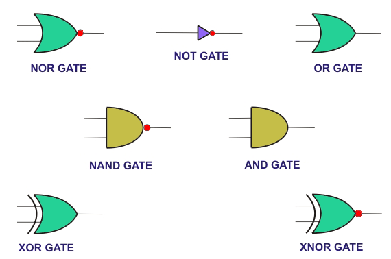
Basic Logic Gates
The three basic logic gates are NOT, AND, and OR. They are called basic because they can create any Boolean expression or function, forming the foundation for all other types of logic gates.
NOT Gate
A NOT gate has one input and one output. It performs the logical negation or inversion operation on its input. This means that it outputs the opposite value of its input. If the input is “0”, the output is “1”, and vice versa. The symbol and truth table for a NOT gate is shown below.
| Input | Output |
|---|---|
| 0 | 1 |
| 1 | 0 |
AND Gate
An AND gate can have two or more inputs but only one output. It performs the logical conjunction operation on its inputs. This means that it outputs “1” only if all its inputs are “1”. Otherwise, it outputs “0”. The symbol and truth table for a two-input AND gate is shown below.
| Input A | Input B | Output |
|---|---|---|
| 0 | 0 | 0 |
| 0 | 1 | 0 |
| 1 | 0 | 0 |
| 1 | 1 | 1 |
OR Gate
An OR gate can have two or more inputs but only one output. It performs the logical disjunction operation on its inputs. This means that it outputs “1” if at least one of its inputs is “1”. Otherwise, it outputs “0”. The symbol and truth table for a two-input OR gate is shown below.
| Input A | Input B | Output |
|---|---|---|
| 0 | 0 | 0 |
| 0 | 1 | 1 |
| 1 | 0 | 1 |
| 1 | 1 | 1 |
Universal Logic Gates
The two universal logic gates are NAND and NOR. They are called universal because they can be used to construct any other type of logic gate or function. They are also simpler and more efficient to implement using transistors than the basic gates.
NAND Gate
A NAND gate combines an AND gate followed by a NOT gate. It performs the logical negation of the AND operation. It outputs “0” only if all its inputs are “1”; otherwise, it outputs “1”. The symbol and truth table for a two-input NAND gate are shown below.
| Input A | Input B | Output |
|---|---|---|
| 0 | 0 | 1 |
| 0 | 1 | 1 |
| 1 | 0 | 1 |
| 1 | 1 | 0 |
NOR Gate
A NOR gate is a combination of an OR gate followed by a NOT gate. It performs the logical negation of the disjunction operation on its inputs. This means that it outputs “1” only if all its inputs are “0”. Otherwise, it outputs “0”. The symbol and truth table for a two-input NOR gate is shown below.
| Input A | Input B | Output |
|---|---|---|
| 0 | 0 | 1 |
| 0 | 1 | 0 |
| 1 | 0 | 0 |
| 1 | 1 | 0 |
Exclusive Logic Gates
The two exclusive logic gates are XOR and XNOR. They are also known as parity gates because they can be used to check or generate parity bits for error detection or correction.
XOR Gate
An XOR gate can have two or more inputs but only one output. It performs the logical exclusive disjunction operation on its inputs. This means that it outputs “1” if an odd number of its inputs are “1”. Otherwise, it outputs “0”. The symbol and truth table for a two-input XOR gate is shown below.
| Input A | Input B | Output |
|---|---|---|
| 0 | 0 | 0 |
| 0 | 1 | 1 |
| 1 | 0 | 1 |
| 1 | 1 | 0 |
XNOR Gate
An XNOR gate is a combination of an XOR gate followed by a NOT gate. It performs the logical negation of the exclusive disjunction operation on its inputs. This means that it outputs “1” if an even number of its inputs are “1”. Otherwise, it outputs “0”. The symbol and truth table for a two-input XNOR gate are shown below.
| Input A | Input B | Output |
|---|---|---|
| 0 | 0 | 1 |
| 0 | 1 | 0 |
Implementation of Digital Logic Gates
Digital logic gates can be made using technologies like transistors, diodes, relays, pneumatic devices, optical devices, and molecular devices. The most common method is using transistors, which are semiconductor devices acting as electronic switches. Transistors can be bipolar junction transistors (BJTs) or metal-oxide-semiconductor field-effect transistors (MOSFETs).
Transistor-Transistor Logic (TTL)
TTL is a logic family that uses BJTs to implement digital logic gates. BJTs are composed of three regions: a base, a collector, and an emitter. The base controls the current flow between the collector and the emitter. When a small current is applied to the base, a larger current flows from the collector to the emitter, turning the transistor on. When no current is applied to the base, no current flows from the collector to the emitter, turning the transistor off.
TTL logic gates use multiple transistors connected in various configurations to perform logical operations on the input signals. The input signals are applied to the bases of the transistors, while the output signal is taken from the collector or the emitter of one or more transistors. The output signal is usually compatible with the input signal, meaning that they have the same voltage levels for logic “0” and logic “1”. This allows TTL gates to be cascaded without any additional components.
TTL logic gates operate on positive logic, meaning that a high voltage level (usually +5 volts) represents logic “1” and a low voltage level (usually 0 volts) represents logic “0”. Any voltage between 2 and 5 volts is considered high, while any voltage below 0.8 volts is considered low. Any voltage in between these ranges may cause the gate to malfunction due to noise or interference.
TTL logic gates have some advantages and disadvantages compared to other logic families. Some of the advantages are:
- They are fast and reliable.
- They have a high noise immunity and fan-out (the number of inputs that can be connected to output without affecting its performance).
- They are widely available and inexpensive.
Some of the disadvantages are:
- They consume more power than other logic families.
- They generate more heat than other logic families.
- They have a limited operating voltage range (usually between 4.75 and 5.25 volts).
Complementary Metal-Oxide-Semiconductor (CMOS)
CMOS is a logic family that uses MOSFETs to implement digital logic gates. MOSFETs are composed of four terminals: a gate, a source, a drain, and a body. The gate controls the current flow between the source and the drain. When a voltage is applied to the gate, an electric field is created in the body region, forming a channel that allows current to flow from the source to the drain, turning the transistor on. When no voltage is applied to the gate, no channel is formed, and no current flows from the source to the drain, turning the transistor off.
CMOS logic gates use complementary pairs of MOSFETs connected in series or parallel configurations to perform logical operations on the input signals. The input signals are applied to the gates of the MOSFETs, while the output signal is taken from the source or drain of one or more MOSFETs. The output signal is usually compatible with the input signal, meaning that they have the same voltage levels for logic “0” and logic “1”. This allows CMOS gates to be cascaded without any additional components.
CMOS logic gates operate on positive logic, meaning that a high voltage level (usually equal to the supply voltage) represents logic “1” and a low voltage level (usually equal to ground) represents logic “0”. The supply voltage can vary from 3 to 18 volts depending on the type of CMOS chip used.
CMOS logic gates have some advantages and disadvantages compared to other logic families. Some of the advantages are:
- They consume very low power when in a steady state (no switching activity).
- They generate very little heat when in a steady state.
- They have a high noise immunity and fan-out.
- They have a wide operating voltage range.
Some of the disadvantages are:
- They are slower than other logic families when switching states.
- They are more susceptible to damage by electrostatic discharge (ESD).
- They occupy more space than other logic families due to their large number of transistors.
Applications of Digital Logic Gates
Digital logic gates have numerous applications in various fields of engineering and science. Some of them are:
- Digital circuits: Digital logic gates are used to design and implement various digital circuits such as adders, subtracters, multiplexers, demultiplexers, encoders, decoders, registers, counters, flip-flops, memory units, arithmetic and logic units (ALUs), microprocessors, microcontrollers, etc.
- Computer architecture: Digital logic gates are used to design and implement various components of computer architecture, such as instruction set architecture (ISA), central processing unit (CPU), memory hierarchy, input/output (I/O) devices, etc.
- Programming languages: Digital logic gates are used to represent and manipulate logical expressions and data types in programming languages such as C++, Java, Python, etc.
- Cryptography: Digital logic gates are used to implement various cryptographic algorithms such as encryption, decryption, hashing, digital signatures, etc.
- Error detection and correction: Digital logic gates are used to implement various error detection and correction techniques such as parity bits, checksums, cyclic redundancy checks (CRCs), Hamming codes, Reed-Solomon codes, etc.
- Artificial intelligence: Digital logic gates are used to implement various artificial intelligence techniques such as neural networks, fuzzy logic systems, genetic algorithms, etc.
Conclusion
Digital logic gates are essential components of digital systems that perform logical operations on binary inputs and produce a binary output. They can be classified into seven basic types: NOT, AND, OR, NAND, NOR, XOR, and XNOR. Each type of logic gate implements a different Boolean function, which can be expressed by a truth table, a logical expression, or a schematic symbol. Digital logic gates can be implemented using various technologies, such as transistors, diodes, relays, pneumatic devices, optical devices, and molecular devices. The most common technologies are transistor-transistor logic (TTL) and complementary metal-oxide-semiconductor (CMOS), which have different advantages and disadvantages in terms of speed, power consumption, noise immunity, fan-out, operating voltage range, and size. Digital logic gates have numerous applications in various fields of engineering and science, such as digital circuits, computer architecture, programming languages, cryptography, error detection and correction, artificial intelligence, etc. Digital logic gates are the building blocks of modern electronics and computing.


