

- Voltage Definition: Voltage is defined as the potential energy difference per unit charge between two points in an electrical field.
- Understanding Through Analogy: Voltage can be likened to water pressure in a hydraulic system, where higher pressure pushes water through pipes, similar to voltage pushing electrons through a circuit.
- Measurement Units: The standard unit for voltage is the volt, represented by the symbol V, quantifying the energy per unit charge.
- Ohm’s Law Application: Voltage is crucial in Ohm’s Law, calculated as the product of current and resistance, helping determine the potential difference in circuits.
- Practical Measurement: To measure voltage, instruments like voltmeters or multimeters are used, connected in parallel with the circuit element to assess the potential difference accurately.
What is Voltage?
Voltage is the electric potential difference between two points: the work per unit charge to move a test charge between those points in an electric field. In circuit work the usual symbols are V and, in older texts, E. Calling voltage “potential difference per unit charge” would divide volts by coulombs. EMF is the open-circuit source voltage, or the line integral of the non-electrostatic field in a source.
For a water-pressure picture, skip to this section.
The formal definition continues below.
In a static electric field, voltage between two points is the work per coulomb to move a small positive test charge between them. In symbols,

Work is in joules. Charge is in coulombs. One volt is one joule per coulomb.

In a circuit, that is the difference in electric potential energy per coulomb between two nodes, not the stored energy of the whole circuit.
One node sits at a higher potential than another. Voltage is that potential difference, not a difference in how much charge sits on the two nodes.
A potential difference drives current in a closed circuit. Conventional current is drawn from the higher-potential terminal toward the lower. Free electrons in a metal drift the other way, from lower potential toward higher.
For a given resistance, a larger voltage means a larger current (Ohm’s law). With zero potential difference between two nodes, no net current flows between them. Charges still move thermally; there is no directed drift.
Older British cable language also used “electric tension.” A 1 kV class is low voltage in IEC terms (up to 1 kV). 11 kV and 33 kV are medium-voltage distribution classes in many grids. “Super tension” is dated UK jargon, not a universal IEC name for 33 kV.
Definition of Potential Difference as Potential of Electric Field
The field definition uses line integrals of E, as in the stored pair below.
Take two points A and B.
V_A relative to V_B is the work per coulomb associated with moving a positive test charge between A and B in field E. Watch the path limits on the stored integral: texts differ on whether they write the integral from A to B or B to A, and that choice sets the minus sign.
The stored form is

With B as the reference, that difference is also written

A pressure analogy is often used next.
The usual picture is water in pipes (the hydraulic analogy), used only as a teaching aid.
Understanding Voltage By Analogy
In that analogy:
Map the quantities as follows.
- Electric potential (voltage) maps to hydraulic pressure
- Electric current is equivalent to hydraulic water flow rate
- Charge maps to a quantity of water
- An electrical conductor is equivalent to a pipe
Analogy 1
Figure (a) shows two tanks at the same water level. With no pressure difference, no flow runs from one tank to the other.

In Figure (b) the levels differ, so water flows until the levels match.
If you join two cells of different open-circuit voltage with a conductor, current flows. The lower-voltage cell is charged only if polarity allows it and the higher source can source current. They do not always “equalize” like two open tanks: internal chemistry sets each cell voltage.
Analogy 2
A tank sits above ground with a hose at the bottom, as in the figure.

Hose pressure stands in for voltage. The water quantity stands in for charge. More water (a taller head) raises the pressure at the hose.
Drain the tank and the hose pressure falls. A discharging storage battery is a rough parallel: terminal voltage sags and a lamp on that battery runs dimmer, if the lamp is a simple resistive load.
Analogy 3
Work in the electric circuit maps to work in a pumped water loop, as in the figure below.

A pump drives water in a pipe. The pipe stands in for a conducting wire.
The pump’s pressure difference can drive a turbine, so the water does work.
A battery’s potential difference can drive current through a lamp, and that current does electrical work in the lamp.
What is Voltage Measured In (Voltage Units)?
SI Unit of Voltage
The SI unit of voltage is the volt (symbol V), a derived unit named for Alessandro Volta (1745-1827), who built the voltaic pile, an early battery.
Volt in SI Base Units
One volt is the potential difference between two points when one joule is exchanged per coulomb that passes. The stored line (including the “chrage” spelling) is

In SI base units that is  or
or  .
.
Equivalents include W/A and A·Ω, from P = VI and V = IR for the same operating point.
Voltage Formula
A circuit form of voltage is shown below. These Ohm’s-law and power forms hold for a resistor (or another element that obeys V = IR at that instant). The field definition remains V = W/Q.

Voltage Formula 1 (Ohm’s Law)
From Ohm’s law,


Example 1
A current of 4 A flows in a 15 Ω resistance. Find the voltage drop.

Solution:
Given:  ,
, 
Ohm’s law:
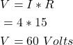
The drop is 60 V.
Voltage Formula 2 (Power And Current)
Instantaneous electrical power into a two-terminal element is v·i. For DC (or RMS on a resistor) P = V I.

Substitute  and you also get P = V²/R, so
(1) 
So V = P/I when that power formula applies:

Example 2
A 48 W lamp draws 2 A. Find the supply voltage, treating P = V I as valid for that lamp at this operating point.

Solution:
Given:  ,
, 
From V = P/I,

The supply voltage is 24 V.
Voltage Formula 3 (Power And Resistance)
From P = V²/R you also have V = √(P R) for a positive DC (or RMS) value:

Example 3
Find the voltage that puts 5 W in a 2 Ω lamp, using V = √(P R). (The stored wording “resistance of current” is the 2 Ω resistance.)

Solution:
Given:  ,
, 
Then
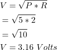
√10 ≈ 3.16, so about 3.16 V across that  lamp.
lamp.
Voltage Circuit Symbol (AC And DC)
AC Voltage Symbol
A common schematic mark for AC (alternating current) voltage is below.

DC Voltage Symbol
A common schematic mark for DC (direct current) voltage is below.

Dimensions of Voltage
Voltage is electric potential energy per unit charge, so its SI dimensions follow from joule/coulomb.
In M, L, T and current A that is  .
.

Some texts use I for the current dimension instead of A, and then write  .
.
How to Measure Voltage
You can measure voltage between two nodes, or between a node and a chosen 0 V reference (chassis or earth, if that is the reference).
On a three-phase system, phase-to-neutral voltage is line-to-neutral (phase voltage). Call it line-to-ground only when that neutral is earthed and you are actually measuring to earth.
Voltage between two phases is line-to-line voltage.
Common instruments:
Voltmeter Method
A voltmeter reads the potential difference between its two leads. Connect it in parallel with the nodes you want.
Put one lead on each node. Do not insert a voltmeter in series as if it were an ammeter: its high resistance would starve the circuit, and you would not be measuring the original voltage.
The same meter can read a drop across one part, or across a string, depending on where the leads sit. The figure shows a resistor measurement.

A moving-coil analog voltmeter is a milliammeter plus a series multiplier. Current in that chain is proportional to the voltage across the instrument, so the scale can be marked in volts. A digital meter uses a different front end, still connected in parallel.
A 9 V battery measurement is shown below. Observe polarity on a DC meter.

Multimeter Method
A multimeter in the volts range is the usual bench tool. Analog and digital types both exist. digital multimeters are now the default for most service work.
Set the range (DC or AC) and put the probes on the two points. A battery check is shown below. Use a CAT rating that matches the circuit.

Potentiometer Method
A laboratory potentiometer compares an unknown voltage with a known reference at null current, so it draws no current from the unknown at balance. The figure is below.

An oscilloscope shows waveform voltage versus time. An electrostatic voltmeter can read high voltage with very small loading.
Difference Between Voltage and Current (Voltage vs Current)
Voltage is potential difference (energy per coulomb) between two points. Current is charge per second through a surface. Voltage can exist with no current (an open switch). Current in a resistor needs a voltage.
In a resistive circuit, voltage is the cause and current is the result. Independent current sources and superconductors are exceptions to that slogan.
Ohm’s law ties V and I through R for that class of device. Equal potentials at two nodes means no current through a resistor joining them.
The table below is stored as-is. Two cells are reversed: a current produces a magnetic field, and separated charge (voltage) is associated with an electric field, not the other way around. Current dimension is I or A, not “MLTA¹”. “Symbol of the current is I” is also in the voltage column in the stored table.
| Voltage | Current |
| The voltage is the difference in potential between two points in an electric field. | The current is the flow of charges between two points in an electric field. |
| The symbol of the current is I. | The SI unit of current is ampere or amp. |
| The symbol of voltage is V or ΔV or E. | The symbol of current is I. |
| Voltage can be measured by using a voltmeter. | Current can be measured by using an ammeter. |
 |  |
 |  |
| In a parallel circuit, the magnitude of voltage remains the same. | In a series circuit, the magnitude of the current remains the same. |
| The voltage creates a magnetic field around it. | The current creates an electrostatic field around it. |
Dimensions of voltage is  | Dimensions of current is  |
| In the hydraulic analogy, electric potential or voltage is equivalent to hydraulic water pressure. | In the hydraulic analogy, electric current is equivalent to hydraulic water flow rate. |
| The voltage is the cause of the current flowing in the circuit. | An electric current is the effect of a voltage. |
Difference Between Voltage and Potential Difference (Voltage vs Potential Difference)
In circuit language, voltage and potential difference are the same quantity. Physics texts sometimes reserve “potential” for a value versus a reference (often infinity) and “potential difference” for V between two finite points. EMF is still a different idea (source voltage / non-conservative work per coulomb).
Both sentences describe the same V = W/Q = V_high − V_low. They are two wordings, not two SI quantities.
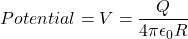
Due to point charge:
Absolute potential of a point charge is often taken versus infinity. Potential difference between two finite radii is V(R1) − V(R2). The stored pair is

A video walkthrough is below.
What is a Common Voltage?
Typical nameplate or system voltages (nominal, not a single worldwide code):
Examples:
- Lead-acid batteries in many small EVs and cars: a 12 V nominal pack is six cells in series. About 2.1 V/cell is a typical open-circuit figure when charged; the nameplate remains 12 V. Series connection adds voltage.
- Solar cells: a silicon cell is often about 0.5 V to 0.6 V open-circuit. Panels series-string those cells for a higher Voc.
- USB 2.0 VBUS: 5 V DC. USB Power Delivery also uses 9 V, 15 V, 20 V and other profiles.
- HVAC transmission often starts around 110 kV to 765 kV. UHV AC and DC projects go higher (including 800 kV to about 1100 kV class). 1200 kV AC has been used on test and limited commercial lines. Local grids use other levels.
- Rail traction examples include 750 V DC, 1.5 kV DC, 3 kV DC, 15 kV 16.7 Hz and 25 kV 50/60 Hz. 12 kV and 50 kV AC exist on some lines. Check the railway you mean.
- Classic TTL and 5 V CMOS: 5 V. Later CMOS families often use 3.3 V, 1.8 V or lower.
- A single rechargeable nickel-cadmium battery cell: 1.2 V nominal.
- Typical zinc-carbon or alkaline flashlight cell: 1.5 V DC nominal.
Typical residential nominals (local codes differ):
- Japan: 100 V single-phase AC (50 Hz or 60 Hz by region)
- United States and Canada: 120 V nominal single-phase to neutral (240 V across the two hots)
- India and Australia: 230 V nominal single-phase (Australia previously quoted 240 V)
Typical industrial three-phase nominals (other levels such as 208 V, 400 V and 600 V also exist):
- Japan: 200 V class three-phase AC is common in industry
- United States: 480 V three-phase is a common industrial nominal
- India: 415 V three-phase is a common industrial nominal (IEC 400 V class)
Applications of Voltage
Where voltage shows up in practice:
- Reading the drop across a resistor or other device
- Series connection of cells to raise pack voltage
- Supply rails from a few volts (for example 5 V logic) up through low-voltage mains such as 415 V three-phase. Voltage itself is not energy; energy is charge times voltage (plus whatever the device converts).
- Extra-low and low voltage for electronics and control
- Higher voltages are also used for
- testing electrical equipment
- Electrostatic printing, Electrostatic painting, Electrostatic coating of material
- Cosmology study of space
- Electrostatic precipitator (air pollution control)
- Jet propulsion laboratory
- X-Ray tubes
- High-power amplifier vacuum tubes
- Mass spectroscopy
- Dielectric testing
- Food and beverage testing
- Electro spraying and spinning applications, electrophotography
- Plasma-based application
- Level sensing
- Induction heating
- Flash lamps
- SONAR


