

- Voltmeter Definition: A voltmeter is defined as an instrument that measures the voltage between two points in an electrical circuit.
- Working Principle of Voltmeter: Voltmeters work by connecting in parallel to the circuit, using high resistance to measure voltage without significantly altering the circuit.
- Types of Voltmeters: Voltmeters come in various types including PMMC, MI, Electrodynamometer, Rectifier, Digital, and Electrostatic voltmeters.
- PMMC Voltmeter: Uses a permanent magnet and moving coil to measure DC voltage with high accuracy and low power consumption.
- Digital Voltmeter (DVM): Measures voltage digitally, providing accurate, fast readings and eliminating parallax error.
What is Voltmeter?
Voltmeter is a voltage meter. Which measures the voltage between the two nodes. We know the unit of potential difference is volts. So it is a measuring instrument which measures the potential difference between the two points.
Working Principle of Voltmeter
The working principle of a voltmeter is that it must be connected in parallel to the circuit where the voltage is measured. This is because a voltmeter has very high resistance. If connected in series, it would nearly stop the current flow, acting like an open circuit.
If it is connected in parallel, than the load impedance comes parallel with the high resistance of the voltmeter and hence the combination will give almost the same the impedance that the load had. Also in parallel circuit we know that the voltage is same so the voltage between the voltmeter and the load is almost same and hence voltmeter measures the voltage.
An ideal voltmeter would have infinite resistance and draw no current, leading to no power loss. However, infinite resistance is not practically achievable.
Classification or Types of Voltmeter
According to the construction principle, we have different types of voltmeters, they are mainly –
- Parmanent Magnet Moving coil (PMMC) Voltmeter.
- Moving Iron (MI) Voltmeter.
- Electro Dynamometer Type Voltmeter.
- Rectifier Type Voltmeter
- Induction Type Voltmeter.
- Electrostatic Type Voltmeter.
- Digital Voltmeter (DVM).
Depending on this types of measurement we do, we have-
- DC Voltmeter.
- AC Voltmeter.
For DC voltmeters PMMC instruments are used, MI instrument can measure both AC and DC voltages, electrodynamometer type, thermal instrument can measure DC and AC voltages as well. Induction meters are not used because of their high cost, inaccuracy in measurement. Rectifier type voltmeter, electrostatic type and also digital voltmeter (DVM) can measure both AC and DC voltages.
PMMC Voltmeter
When current carrying conductor placed in a magnetic field, a mechanical force acts on the conductor, if it is attached to a moving system, with the coil movement, the pointer moves over the scale.
PMMC instruments have parmanent magnets. It is suited for DC measurement because here deflection is proportional to the voltage because resistance is constant for a material of the meter and hence if voltage polarity is reversed, deflection of the pointer will also be reversed so it is used only for DC measurement. This type of instrument is called D’Arnsonval type instrument. It has advantages of having linear scale, power consumption is low, high accuracy.
Major disadvantages are –
It only measures DC quantity, higher cost etc.
Where,
B = Flux density in Wb/m2.
i = V/R where V is the voltage to be measured and R is the resistance of the load.
l = Length of the coil in m.
b = Breadth of the coil in m.
N = No of turns in the coil.
Extension of Range in a PMMC Voltmeter
In the PMMC voltmeters we have the facility of extending the range of measurement of voltage also. Just connecting a resistance in series with the meter we can extend the range of measurement.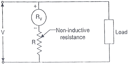
Let,
V is the supply voltage in volts.
Rv is the voltmeter resistance in Ohm.
R is the external resistance connected in series in ohm.
V1 is the voltage across the voltmeter.
Then the external resistance to be connected in series is given by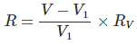
MI Voltmeter
MI instruments mean moving iron instrument. It is used for both AC and DC measurements, because the deflection θ proportional square of the voltage assuming impedance of the meter to be constant, so what ever is polarity of the voltage, it shows directional deflection, further they are classified in two more ways,
- Attraction type.
- Repulsion type.

Where, I is the total current flowing in the circuit in Amp. I = V/Z
Where, V is the voltage to be measured and Z is the impedance of the load.
L is the self inductance of the coil in Henry.
θ is the deflection in Radian.
Attraction type MI Instrument Principle
If an unmagnetised soft iron is placed in the magnetic field, it is attracted towards the coil, if a pointer is attached to the systems and current is passed through a coil as a result of the applied voltage, it creates a magnetic field which attracts iron piece and creates deflecting torque as a result of which pointer moves over the scale.
Repulsion type MI Instrument Principle
When two iron pieces are magnetized with the same polarity by passing a current which done by applying a voltage across the voltmeter than repulsion between them occurs and that repulsion produces a deflecting torque due to which the pointer moves.
The advantages are it measure both AC and DC, it is cheap, low friction errors, Robust etc. It is mainly used in AC measurement because in DC measurement error will be more due to hysteresis.
Electrodynamometer Type Voltmeter
Electrodynamometer instruments are used because they maintain the same calibration for both AC and DC measurements. Once calibrated with DC, they can measure AC without recalibration.
Electrodynamometer Type Voltmeter Principle
We have two coils, fixed and moving coils. If a voltage is applied at the two coils as a result of which current flows two coils it will stay in the zero position due to the development of equal and opposite torque. If the direction of one torque is reversed as the current in the coil reverses, an undirectional torque is produced.
For voltmeter, the connection is a parallel one and both fixed and moving coils are connected in series with non-inductive resistance.
φ = 0 where φ is the phase angle.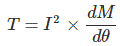
Where, I is the amount of current flowing in the circuit in Amp = V/Z.
V and Z are the applied voltages and impedance of the coil respectively.
M = Mutual inductance of the coil.
Electrodynamometer voltmeters have no hysteresis error and can measure both AC and DC. However, they have a low torque-to-weight ratio, high friction loss, and are more expensive than other types of voltmeters.
Rectifier Voltmeter
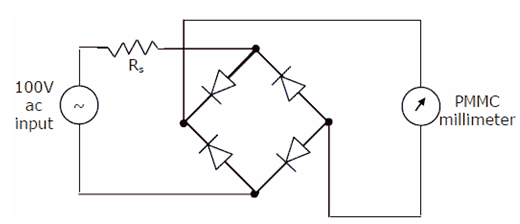
Rectifier Voltmeter Principle
They are used for AC or DC measurements. For DC measurement we have to connect a PMMC meter which measures pulsating DC voltage which measures rectified voltage which is connected across the bridge rectifier.
Advantages of Rectifier Voltmeter
- Can be used in high frequency.
- It has uniform scale for most of the ranges.
Disadvantages of having an error due to temperature decrease in sensitivity in AC operation.
Digital Voltmeters (DVM)
Digital Voltmeters (DVM) Principle
The Digital Voltmeter is an instrument which can give the output voltage not by deflection but directly indicating the value. It is a very good instrument to measure the voltage as it eliminates completely the error due to parallax, approximation in measurement, high-speed reading can be done and it can also be stored in memory for further analysis. The main principle is that the value is measured by the same circuit arrangement but that value is not used to deflect the pointer, but it is fed to the analog to digital converter and displayed as the digital value.
Electrostatic Instruments
Electrostatic Instruments Principle
When electric field created by the charged particles are allowed to act on the conductors which is charged by the current, a deflecting torque is produced. This can be done by using-
- Two electrodes which are oppositely charged in which one of them is fixed and the other is movable.
- Force between two electrodes which causes rotary motion of the moving electrode.

Where, V is the voltage to be measured in volts, C is the value of capacitance in farad and θ is the deflection in radians.
Advantages of the electrostatic meter having low power consumption, can be used for both AC and DC quantities, no hysteresis loss, no stray magnetic field error. Disadvantages are it has non uniform scale, low operating force, it has expansive and the size is large also its construction is not robust.


