

- Definition of Transformer Losses: Losses in a transformer include electrical losses such as core losses and copper losses, which are the difference between input and output power.
- Copper Loss in Transformer: Copper loss is the I²R loss occurring in the primary and secondary windings of the transformer, depending on the load.
- Core Losses in Transformer: Core losses, also known as iron losses, are fixed and do not vary with the load, depending on the core material and design.
- Hysteresis Loss in Transformer: Hysteresis loss occurs due to the energy required to realign the magnetic domains in the transformer’s core material.
- Eddy Current Loss in Transformer: Eddy current loss happens when alternating magnetic flux induces circulating currents in the transformer’s conductive parts, dissipating energy as heat.
Losses in Transformer
An electrical transformer is a static machine, so mechanical loss is not the usual concern. The losses in transformer that matter here are electrical. Loss is input power minus output power. When power is fed to the primary of a transformer, some of it covers core losses in transformer: Hysteresis loss in transformer and Eddy current loss in transformer in the core. Some is lost as I2R heat in the primary and secondary windings, because those windings have internal resistance. The first group is core loss or iron loss in transformer. The second is ohmic loss or copper loss in transformer. Stray loss is a further term: stray fluxes linking mechanical structure and winding conductors.
Copper Loss in Transformer
Copper loss is I²I2R loss, with I12R1 on the primary and I22R2 on the secondary. I1 and I2 are the primary and secondary currents, and R1 and R2 are the winding resistances. Those currents follow the load, so copper loss in a transformer follows the load.
Core Losses in Transformer
Hysteresis loss and eddy current loss both depend on the magnetic properties of the material in the core of transformer and on its design. Those losses in transformer are fixed and do not follow load current. So core losses in transformer, also called iron loss in transformer, can be treated as constant across the load range.
Hysteresis loss in transformer is written
Eddy current loss in transformer is written
Where, Kh = Hysteresis constant.
Ke = Eddy current constant.
Kf = form constant.
Copper loss can be written as
IL2R2′ + Stray loss
Where IL = I2 = load of transformer, and R2′ is the resistance of the transformer referred to the secondary.
Hysteresis loss and eddy current loss are treated next in more detail.
Hysteresis Loss in Transformer
Hysteresis loss in transformers can be described in two ways: physically and mathematically.
Physical Explanation of Hysteresis Loss
The magnetic core of transformer is made of ′Cold Rolled Grain Oriented Silicon Steel′. Steel is a strong ferromagnetic material and is readily magnetized. When magnetic flux passes through it, the steel behaves as a magnet. Ferromagnetic substances contain many domains. A domain is a small region in which all dipoles point the same way, so each domain is a tiny permanent magnet placed at random in the structure. Those random domains cancel, so the net magnetic field of the material is zero. Apply an external magnetic field (mmf) and the domains line up with the field. Remove the field and most domains go random again, but some stay aligned. Those leftover domains leave the specimen slightly magnetized: “Spontaneous Magnetism”. An opposite mmf is then needed to cancel it. The mmf in a transformer core is alternating, so every cycle reverses the domains. That extra work consumes electrical energy: hysteresis loss of the transformer.
Mathematical Explanation of Hysteresis Loss in Transformer
Determination of Hysteresis Loss

Take a ring of ferromagnetic specimen of circumference L meter, cross-sectional area a m2 and N turns of insulated wire as in the figure.
Let the current in the coil be I amp,
Magnetizing force,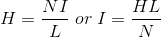
Let the flux density at this instant be B.
Total flux through the ring, Φ = BXa Wb
The coil current is alternating, so the flux in the iron ring is alternating, and the induced emf (e′) is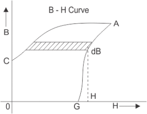
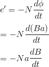
By Lenz,s law that induced emf opposes the current, so the source must supply an equal opposite emf to keep I in the coil. Applied emf,
Energy consumed in a short time dt, while flux density changes,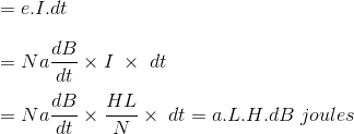
Total work done or energy consumed during one complete cycle of magnetism is
aL is the volume of the ring and H.dB is the area of the elementary strip of the B – H curve above,
Energy consumed per cycle = volume of the ring × area of hysteresis loop.
In a transformer that ring is the magnetic core. The work done is electrical energy lost in the core: hysteresis loss in the transformer.
What is Eddy Current Loss?
In a transformer we feed alternating current to the primary. That current produces alternating magnetizing flux in the core. The flux linking the secondary induces voltage there, so current flows in the connected load. Some of the alternating flux also links other conducting parts, such as the steel core or iron body. Those linkages induce local emfs, and the resulting currents circulate in those parts. The circulating current does not reach the output; it appears as heat. The name for that energy is eddy current loss of the transformer. The account above is broad and simple. A fuller treatment is outside this chapter.


