

- Induction Type Meters Definition: Induction type meters are devices used to measure electrical energy in homes and industries by using the interaction of fluxes and alternating currents.
- Working Principle: These meters operate by generating torques from two alternating currents, causing a metallic disc to move.
- Types of Induction Meters: The two main types are single phase and three phase induction meters.
- Single Phase Meter Components: Key parts include the driving system with electromagnets, a floating aluminum disc in the moving system, a braking system with a permanent magnet, and a counting system to record revolutions.
- Advantages: Induction type meters are inexpensive, have a high torque-to-weight ratio, and are accurate across different temperatures and loads.
The working principle and construction of an induction type meter are simple and easy to understand, making them popular for measuring energy in homes and industries. In all induction meters, two fluxes are produced by different alternating currents on a metallic disc. These alternating fluxes create an induced emf. This emf interacts with the alternating current on the opposite side, producing torque.
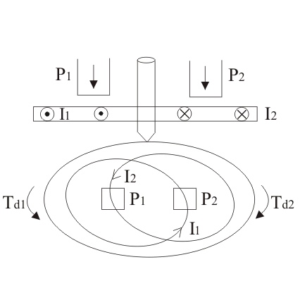
Similarly, the emf produced at point two interacts with the alternating current at point one, creating torque in the opposite direction. These opposing torques cause the metallic disc to move.
This is basic principle of working of an induction type meters. Now let us derive the mathematical expression for deflecting torque. Let us take flux produced at point one be equal to F1 and the flux and at point two be equal to F2. Now the instantaneous values of these two flux can written as:

Where, Fm1 and Fm2 are respectively the maximum values of fluxes F1 and F2, B is phase difference between two fluxes.
We can also write the expression for induced emf’s at point one be
at point two. Thus we have the expression for eddy currents at point one is
Where, K is some constant and f is frequency.
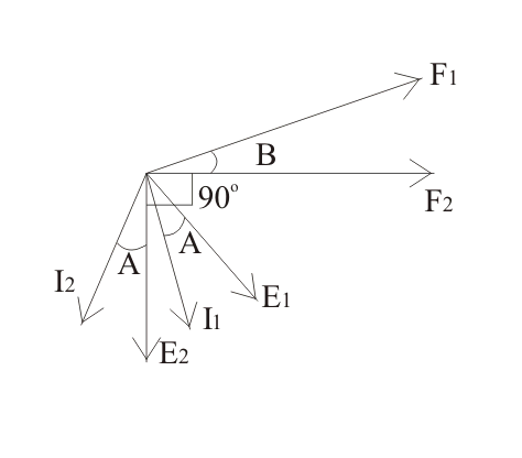
Let us draw phasor diagram clearly showing F1, F2, E1, E2, I1 and I2. From phasor diagram, it clear that I1 and I2 are respectively lagging behind E1 and E2 by angle A.
The angle between F1 and F2 is B. From the phasor diagram the angle between F2 and I1 is (90-B+A) and the angle between F1 and I2 is (90 + B + A). Thus we write the expression for deflecting torque as
Similarly the expression for Td2 is,
The total torque is Td1 – Td2, on substituting the the value of Td1 and Td2 and simplying the expression we get
Which is known as the general expression for the deflecting torque in the induction type meters. Now there are two types of induction meters and they are written as follows:
- Single phase type
- Three phase type induction meters.

Here we are going to discuss about the single phase induction type in detail. Given below is the picture of single phase induction type meter.
Single phase induction type energy meter consists of four important systems which are written as follows:
Driving System:
Driving system consists of two electromagnets on which pressure coil and current coils are wounded, as shown above in the diagram. The coil which consisted of load current is called current coil while coil which is in parallel with the supply voltage (i.e. voltage across the coil is same as the supply voltage) is called pressure coil. Shading bands are wounded on as shown above in the diagram so as to make angle between the flux and and applied voltage equal to 90 degrees.
Moving System:
To reduce friction, a floating shaft energy meter is used. The aluminum disc, made of very light material, does not touch any surface and floats in the air. This happens because the disc has small magnets on both upper and lower surfaces. The upper magnet is attracted to an electromagnet in the upper bearing, while the lower magnet is attracted to the lower bearing magnet. These opposite forces make the aluminum disc float.
Braking System:
A permanent magnet is used to produce breaking torque in single phase induction energy meters which are positioned near the corner of the aluminium disc.
Counting System:
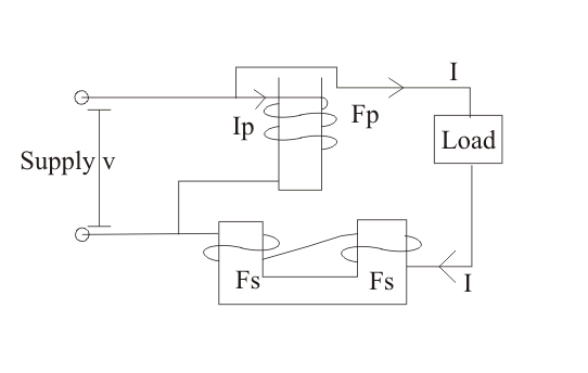
Numbers marked on the meter are proportion to the revolutions made by the aluminium disc, the main function of this system is to record the number of revolutions made by the aluminium disc. Now let us look at the working operation of the single phase induction meter. In order to understand the working of this meter let us consider the diagram given below:
We assume the pressure coil is highly inductive and has many turns. The current in the pressure coil, Ip, lags behind the voltage by 90 degrees, producing flux F. Flux F is divided into two parts: Fg and Fp.
- Fg which moves on the small reluctance part across the side gaps.
- Fp: It is responsible for the production of driving torque in the aluminium disc. It moves from high reluctance path and is in phase with the current in the pressure coil. Fp is alternating in nature and thus emf Ep and current Ip. The load current which is shown in the above diagram is flowing through the current coil produces flux in the aluminium disc, and due this alternating flux there on the metallic disc, an eddy current is produced which interacts with the flux Fp which results in production of torque. As we have two poles, thus two torques are produced which are opposite to each other. Hence from the theory of induction meter that we have discussed already above the net torque is the difference of the two torques.
Advantages of Induction Type Meters
Following are the advantages of induction type meters:
- They are inexpensive as compared to moving iron type instruments.
- They have high torque is to weight ratio as compared to other instruments.
- They retain their accuracy over wide range of temperature as well as loads.

")

")