

- Electrostatic Instrument Definition: An electrostatic instrument is defined as a device that uses static electrical fields to measure voltage, usually high voltages.
- Working Principle: Electrostatic instruments generate deflecting torque through the force between oppositely charged plates.
- Construction Types: These instruments can have either fixed and movable plates or rotary plates to create force and torque.
- Torque Equation: For rotary types, the deflecting torque is directly proportional to the square of the voltage, leading to a non-uniform scale.
- Range Extension: The measurement range can be extended using resistance potential dividers or capacitor multipliers.
Working Principle of Electrostatic Type Instruments
Electrostatic instruments use the force associated with an electric field and a changing capacitance to produce deflection. They are primarily used as voltmeters, especially where high input impedance or high-voltage measurement is needed. The term static electrical field describes DC operation, but the voltage-squared torque also permits calibrated AC measurements. Construction varies with the required voltages and sensitivity.
Construction of Electrostatic Type Instruments
- In a linear arrangement, one electrode is fixed and another can translate. Applied voltage creates an attractive force toward greater capacitance. A spring or feedback system balances that force at the measured position.
- In a rotary arrangement, a movable vane turns relative to fixed vanes toward greater capacitance. The geometry converts electrostatic force into torque.
Force and Torque Equation of Electrostatic Type Instrument
The energy method gives the force equation for linear electrostatic instruments. 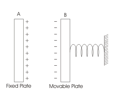
Let plate A be fixed and plate B move along coordinate x. Together they form a capacitance C(x). At a constant applied voltage V, the field stores energy while electrostatic force F acts in the direction that increases capacitance. At equilibrium, this force equals the spring force. The stored field energy is:

For small changes dV and dx, plate B moves while the source transfers charge. Mechanical work is F.dx. The charging current follows the differential relation: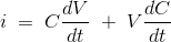
The corresponding source input energy, expressed through the electric current, is:
Keeping first-order differential terms gives the following change in stored energy:
Energy conservation equates source input to increased field energy plus mechanical work:
For constant voltage, the resulting force magnitude is one-half V squared times the capacitance gradient dC/dx:
The same method gives the torque equation for rotary electrostatic type instruments. The diagram shows the angular geometry: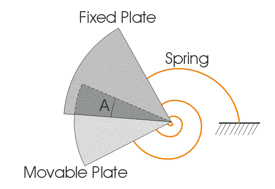
For rotary electrostatic instruments, use angular displacement A and the capacitance gradient dC/dA. The deflecting torque is: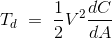
With spring controlling torque Tc = K × A, the steady deflection is:
Deflection therefore follows voltage squared when dC/dA is constant, giving a crowded lower end and a non-uniform voltage scale. Because polarity disappears on squaring, the movement can indicate DC and the RMS value of AC within its calibrated frequency and waveform conditions. A quadrant electrometer is one rotary implementation; its usable range depends on its construction and insulation. Voltage dividers can extend the range of electrostatic voltmeters.
(a) A resistance potential divider applies only a known fraction of the total voltage to the instrument. The diagram shows the arrangement.
For DC, let a high-side resistance R be in series with a low-side resistance r, and connect the electrostatic capacitor across r. With negligible leakage and loading, the multiplying factor is (R + r)/r. The electrical resistance values, voltage ratings and power ratings must suit the application. For AC, instrument capacitance, stray capacitance and resistor capacitance change the divider ratio and phase, so a compensated divider and frequency-specific calibration are required.
(b) A capacitor-divider, or capacitor-multiplier, connection places a known series capacitor with the instrument to reduce the voltage applied to it.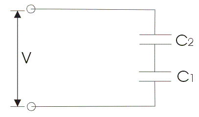
Let C1 be the voltmeter’s capacitance and C2 the series capacitor. The same charge flows in the ideal series combination, so voltage divides inversely with capacitance.

The voltmeter impedance is Z1 = 1/jωC1, and the ideal total series impedance is:

The applied-voltage to meter-voltage ratio is Z/Z1, which equals 1 + C1/C2 for ideal capacitors. Stray capacitance, dielectric loss and voltage dependence require calibration of a practical high-voltage divider.
Advantages of Electrostatic Type Instruments
The main advantages of electrostatic type instruments are:
- Voltage-squared torque permits measurement of either polarity of DC and calibrated RMS measurement of AC within the instrument’s frequency limits.
- DC input current is limited mainly by leakage. On AC, the instrument draws a small capacitive current and may have dielectric loss.
- Large electrode spacing and suitable insulation allow direct or divided measurement of high voltage.
Disadvantages of Electrostatic Type Instruments
The main disadvantages are:
- High-voltage insulation, guarding and low-friction construction can make the instrument large and costly.
- A voltage-squared response produces a non-uniform scale unless the geometry or readout linearises it.
- Electrostatic operating force is small, so friction, stray fields, vibration and contamination can cause a large error.


