

- Electrodynamometer Wattmeter Definition: An electrodynamometer type wattmeter measures electrical power by using the interaction between magnetic fields and electric currents.
- Working Principle: It operates on the principle that a current-carrying conductor in a magnetic field experiences a mechanical force causing deflection.
- Construction: It includes a moving coil connected across the voltage and a fixed coil divided into two parts, connected in series with the load.
- Advantages: This wattmeter can measure both AC and DC quantities, has a uniform scale, and is highly accurate.
- Errors: Common errors include those due to inductance, capacitance, mutual inductance, connections, eddy currents, vibration, temperature, and stray magnetic fields.
Before examining the construction of an electrodynamometer type wattmeter, it’s important to understand its working principle. This wattmeter operates on a simple principle: when a current-carrying conductor is placed in a magnetic field, it experiences a mechanical force, causing the conductor to deflect.
Construction and Working Principle of Electrodynamometer Type Wattmeter
Now let us look at constructional details of electrodynamometer. It consists of following parts.
There are two types of coils present in the electrodynamometer. They are :
Moving Coil
The moving coil moves the pointer with the help of a spring control instrument. To prevent overheating, a limited current flows through the moving coil by connecting a high-value resistor in series. The air-cored moving coil is mounted on a pivoted spindle and can move freely. In an electrodynamometer type wattmeter, the moving coil acts as a pressure coil and is connected across the voltage, so the current through it is proportional to the voltage.
Fixed Coil
The fixed coil is divided into two equal parts and these are connected in series with the load, therefore the load current will flow through these coils. Now the reason is very obvious of using two fixed coils instead of one, so that it can be constructed to carry considerable amount of electric current. These coils are called the current coils of electrodynamometer type wattmeter. Earlier these fixed coils are designed to carry the current of about 100 amperes but now the modern wattmeter are designed to carry current of about 20 amperes in order to save power.
Control System
Out of two controlling systems i.e.
- Gravity control
- Spring control, only spring controlled systems are used in these types of wattmeter. Gravity controlled system cannot be employed because there will be appreciable amount of errors.
Damping System
Air friction damping is used because eddy current damping can distort the weak operating magnetic field, leading to errors.
Scale
There is uniform scale which is used in these types of instrument as moving coil moves linearly over a range of 40 degrees to 50 degrees on either side.
Now let us derive the expressions for the controlling torque and deflecting torques. In order to derive these expressions let us consider the circuit diagram given below: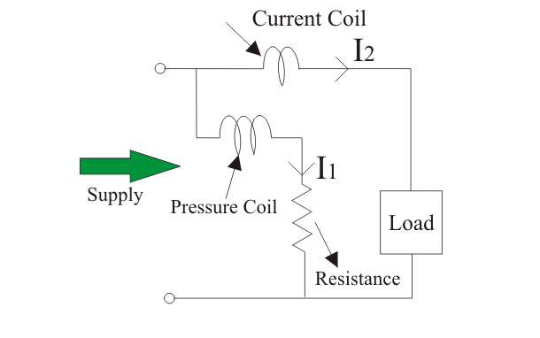
We know that instantaneous torque in electrodynamic type instruments is directly proportional to the product of instantaneous values of currents flowing through both the coils and the rate of change of flux linked with the circuit.
Let I1 and I2 be the instantaneous values of currents in pressure and current coils respectively. So the expression for the torque can be written as: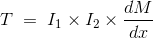
Where, x is the angle.
Now let the applied value of voltage across the pressure coil be
Since the electrical resistance of the pressure coil is very high, we can neglect its reactance compared to its resistance. Thus, the impedance is equal to its electrical resistance, making it purely resistive.
The expression for instantaneous current can be written as I2 = v / Rp where Rp is the resistance of pressure coil.
If there is phase difference between voltage and electric current, then expression for instantaneous current through current coil can be written as
As current through the pressure coil is very very small compared to the current through current coil hence current through the current coil can be considered as equal to total load current.
Hence the instantaneous value of torque can be written as
Average value of deflecting torque can be obtained by integrating the instantaneous torque from limit 0 to T, where T is the time period of the cycle.
Controlling torque is given by Tc = Kx where K is spring constant and x is final steady state value of deflection.
Advantages of Electrodynamometer Type Wattmeter
Following are the advantages of electrodynamometer type wattmeter and they are written as follows:
- Scale is uniform upto a certain limit.
- They can be used for both to measure ac as well dc quantities as scale is calibrated for both.
Errors in Electrodynamometer Type Wattmeter
Following are the errors in the electrodynamometer type wattmeters:
- Errors in the pressure coil inductance.
- Errors may be due to pressure coil capacitance.
- Errors may be due to mutual inductance effects.
- Errors may be due connections.(i.e. pressure coil is connected after current coil)
- Error due to Eddy currents.
- Errors caused by vibration of moving system.
- Temperature error.
- Errors due to stray magnetic field.


