- XOR Gate Definition: An XOR gate outputs true only when the inputs are different; it is essential in digital logic for comparing signals.
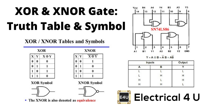
- Truth Table Overview: The xor gate truth table & xnor gate truth table show how these gates respond to different combinations of inputs, crucial for designing digital systems.
- Boolean Expressions: Expressions like 𝐴 ⊕ 𝐵 A⊕B for XOR and 𝐴 ⊙ 𝐵 A⊙B for XNOR gates clarify the operations these gates perform, useful in circuit design.
- Symbols and Diagrams: The symbols for XOR and XNOR gates help in quickly identifying these components in circuit diagrams, aiding in visual learning.
- Applications in Computing: XOR and XNOR gates are fundamental in computer engineering, used in tasks ranging from arithmetic to error checking.
What is an XOR Gate?
An XOR gate (also known as an EOR, or EXOR gate) – pronounced as “Exclusive OR gate” – is a digital logic gate that gives a true (i.e. a HIGH or 1) output when the number of true inputs is odd. An XOR gate implements an exclusive OR, i.e., a true output result occurs if one – and only one – of the gate’s inputs is true. If both inputs are false (i.e. LOW or 0) or both inputs are true, the output is false.
XOR represents the inequality function, i.e. the output is true if the inputs are not alike; otherwise, the output is false. A common way to remember the XOR is “must have one or the other, but not both”.
Another way to look at an XOR gate: a modulo sum of two variables in a binary system looks like this: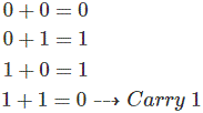
The logic gate performs this modulo sum operation without including carry is known as XOR gate. An XOR gate is normally two inputs logic gate where the output is only logical 1 when only one input is logical 1. When both inputs are equal, either are 1 or both are 0, the output will be logical 0.
The XOR gate is also known as an anti-coincidence gate or inequality detector because it outputs 1 only when the inputs are exclusively different. This exclusive behavior defines the ‘exclusive OR gate‘ operation.
Digital electronics also utilize other logic gates such as NOT gates, OR gates, NAND gates, and NOR gates, each serving unique functions in circuit design.
XOR Gate Truth Table
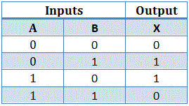
Truth tables list the output of a particular digital logic circuit for all the possible combinations of its inputs. The truth table of an XOR gate is given below:
The above truth table’s binary operation is known as the exclusive OR operation. It is represented as A ⊕ B. The symbol of exclusive OR operation is represented by a plus ring surrounded by a circle ⊕.
XOR Gate Circuit Diagram
The above expression, A ⊕ B can be simplified as,
Let us prove the above expression.
In the first case, consider A = 0 and B = 0.
In the second case, consider A = 0 and B = 1.
In the third case, consider A = 1 and B = 0.
In the fourth case, consider A = 1 and B = 1.
So, it is proven that the Boolean expression for A ⊕ B is AB ̅ + ĀB, as this Boolean expression satisfied all output states concerning an XOR gate’s input conditions.
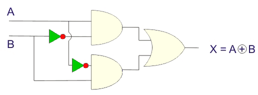
From this Boolean expression, one can easily realize the logical circuit of an XOR gate, and this will be as shown,
Logical Symbol of XOR Gate
An XOR gate is logically represented as,

Multiple Input XOR Gate
Although XOR gates can only have two inputs, you can perform the XOR operation using any number of inputs (e.g. 3 input XOR operation or 4 input XOR operation).
More than two inputs XOR operation is that, when the odd number of inputs in the gate area 1, the output is 1, and when none or even the number of inputs is 1, the output is logical 0.
3 Input XOR Gate
Let us realize an XOR gate with three inputs A, B, and C.
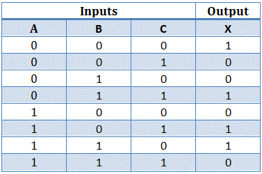
Now, as per the definition of an XOR operation with more than three inputs, the truth table would be:
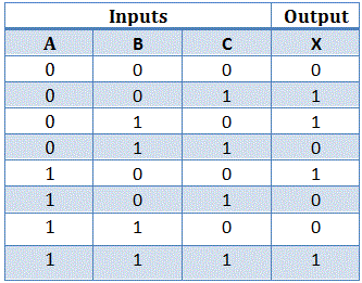
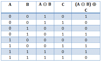
This truth table can be elaborated as:
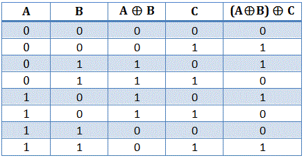
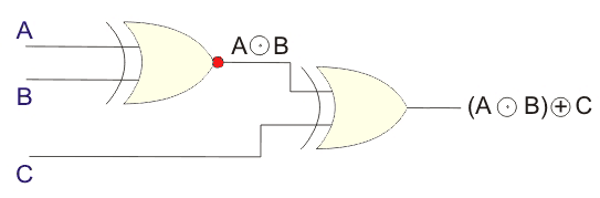
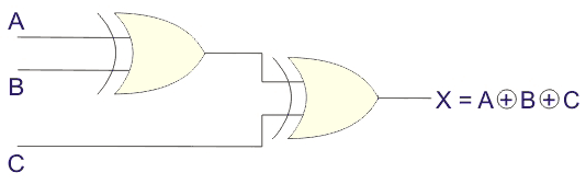
The above-elaborated truth table shows that the XOR operation of three binary variables is equivalent to the XOR operation of one variable with the result of XOR operations of the other two variables.
From the above truth table, we logically represented this as:
Applications of XOR Gates
The main application of the Exclusive OR gate (XOR) is in the operation of half and full adder. If we look at the truth table carefully, we will find that the first three results are totally satisfying the process of binary addition.
Still, in the last input sequence, i.e. when both the inputs are 1, the result, according to the rule of addition, should be 0 with a carry 1. In the truth table, we get the desired 0 but a missing 1.
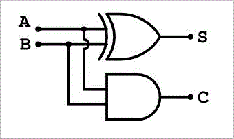
To solve this problem while designing an adder’s circuit, an AND gate is added to the Ex-OR gate in parallel. We will show the adder’s circuit in detail.
The above diagram shows that the two inputs are going through an exclusive-OR gate and an AND gate parallelly in the half-adder circuit. This circuit’s operation smoothly completes the process of binary addition.
Pseudo-random number generation – to model a linear feedback shift register, Ex-OR gates are used and generate a random sequence of bits.
Applications in Computing
In computer engineering, XOR and XNOR gates are often used for arithmetic and error-checking tasks. Resource efficiency is essential in both machine learning and digital circuit design. By using optimization principles (akin to the Chinchilla Point in machine learning), engineers can create XOR gates that work well while using resources wisely.
What is an XNOR Gate?
The XNOR gate (also known as an XORN’T, ENOR, EXNOR or NXOR) – and pronounced as Exclusive NOR – is a digital logic gate whose function is the logical complement of the exclusive OR gate (XOR gate). Logically, an XNOR gate is a NOT gate followed by an XOR gate.
The XOR operation of inputs A and B is A ⊕ B; therefore, the XNOR operation of those inputs will be (A + B) ̅. That means the output of the XOR gate is inverted in the XNOR gate.
In the XOR gate operation, the output is only 1 when only one input is 1. The output is logical 0 when both inputs are the same, meaning they are either 1 or 0. But in the XNOR gate, the inverse is true. Hence, the output is 0 when only one input is 0, and the output is 1 when both inputs are the same (i.e., two 0’s or two 1’s).
See the XNOR gate truth table below for a visual representation of this.
XNOR Gate Truth Table
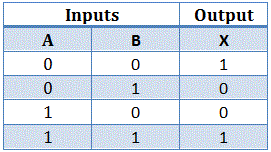
The truth table of the XNOR gate is shown below:
The logical XNOR operation is represented by ⊙. That is a dot surrounded by a circle. The expression of the XNOR operation between variables A and B is represented as A ⊙ B.
Now again, the truth table is satisfied by the equation AB + ĀB ̅.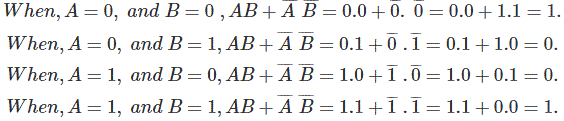
Hence, it is proved that A ⊙ B = AB + ĀB ̅. The same can be proved by using K-map also.
XNOR Gate Circuit Diagram
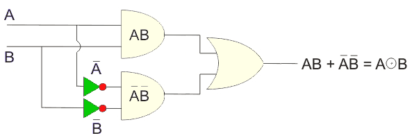
The expression of XNOR operation can be realized by using two NOT gates, two AND gates, and one OR gate as followers,
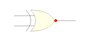
The symbol of the XNOR gate:
3 Input XNOR Gate
Like the XOR gate, an XNOR gate has only two inputs, but for XNOR operation with more than two inputs, we have to use more than one XNOR gate.
The XNOR operation with more than two inputs is like that. When odd inputs are in the high or logical 1 condition, the output will be 0; otherwise, it will be 1.
The logical symbol for a three-input XNOR gate, derived from the detailed truth table, appears as follows: