
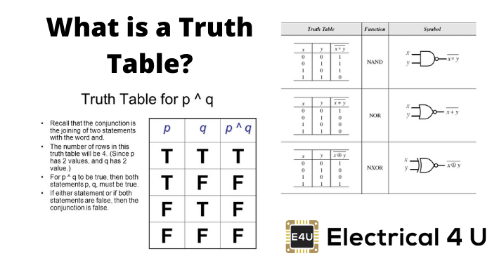
- Truth Table Definition: A truth table is a mathematical table that shows the output of a digital logic circuit for all possible input combinations.
- Structure and Use: Truth tables have columns for each input and the output, and they help deduce logical expressions for circuits.
- NOT Gate: A NOT gate outputs the opposite of the input, turning 0 into 1 and 1 into 0.
- AND Gate: An AND gate outputs 1 only if all inputs are 1; otherwise, it outputs 0.
- XOR Gate: An XOR gate outputs 1 when inputs are different and 0 when they are the same, often used as a parity checker.
What is a Truth Table?
A truth table is a mathematical table that lists the output of a particular digital logic circuit for all the possible combinations of its inputs. These truth tables can be used to deduce the logical expression for a given digital circuit, and are used extensively in Boolean algebra.
A truth table has one column for each input variable (commonly represented as P and Q, x and y, or a and b), and one final column showing all of the possible results of the logical operation that the table represents (for example, P AND Q).
Each row of the truth table contains one possible configuration of the input variables (for example, P=false [0] Q=true [1]), and the result of the operation for those values (continuing the example, P AND Q=false [0]).
Logic gate questions are a great way to test your knowledge on the topic of truth tables.
NOT Gate or an Inverter Truth Table

A NOT gate is a single-input, single-output logic device where the output is always the opposite of the input.
If the input is 1, the output is 0, and if the input is 0, the output is 1. This is symbolically written as Y = X̅.
AND Gate Truth Table
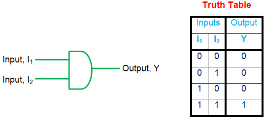
An AND gate is a basic gate with multiple inputs and a single output. The output is high (1) only if all inputs are high; otherwise, the output is low (0), as shown by the truth table. The logical expression for this gate is Y = I1.I2.
OR Gate Truth Table
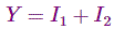
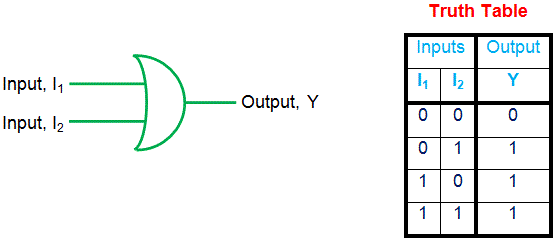
OR is a type of basic gate with multi-input, single-output characteristics. Here the output is zero only if all of its input bits are zero as indicated by the truth table of 2-input OR gate. The logical expression for the OR gate is given as
NAND Gate Truth Table
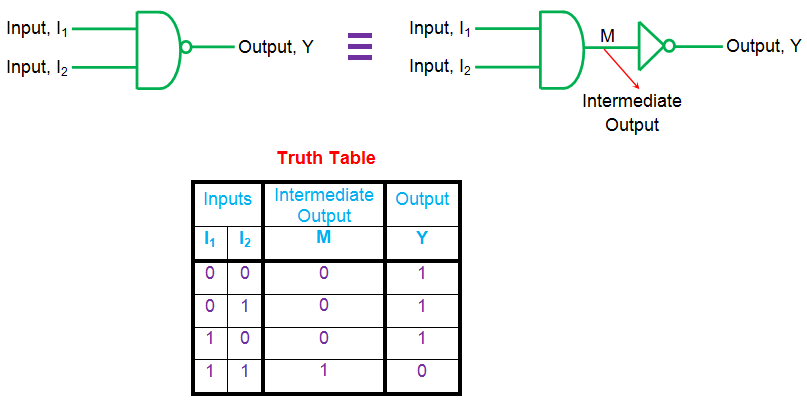
NAND gate is logically equivalent to AND gate followed by a NOT gate. The truth table for this gate shows that the output of the NAND gate is low only if all of its inputs are high (else it is one).
This implies that the output of the NAND gate is the negated output of the AND gate, represented by the intermediate result M in the above truth table. The logical expression of a NAND gate is given by

NOR Gate Truth Table

NOR gate is a result of combining NOT gate with an OR gate. Thus its output is the negation of OR gate output which implies that it has high output only if all of its inputs are low.
However, for any other combination of inputs, the output will be low as shown by the truth table. A logical expression for the same can be given as

XOR Gate Truth Table

XOR gate is a logical device that has its output high only when its inputs are different, as shown by the truth table. This means that non-identical inputs result in a high output of the gate while identical input bits cause the gate output to go low.
Logically this is given by 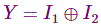 Further in its expanded form, one gets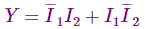
In general XOR gate is used as a parity checker and can have multiple inputs.
XNOR Gate Truth Table

XNOR gate is a result of combining the XOR gate with a NOT gate, which means that the output will be the inverted form of the XOR outputs.
Thus one gets high output for identical inputs and low output for non-identical inputs, as shown by the truth table. The logical expression for the XNOR gate is given by
This gate can also have multiple inputs and serves as a parity checker.


