

- Parity Checking Definition: Parity checking is a method that uses an extra bit, called a parity bit, to detect single-bit errors in data transmission.
- Even Parity: Even parity ensures that the total number of 1s in the data word and the parity bit is even, helping detect errors.
- Odd Parity: Odd parity ensures that the total number of 1s in the data word and the parity bit is odd, providing another method for error detection.
- Parity Generator: A parity generator is a combinational logic circuit at the transmitter end that creates the parity bit based on the data word.
- Parity Checker: A parity checker is a combinational logic circuit at the receiver end that checks the parity of the received data word to detect errors.
Parity generators and checkers are devices that help ensure error-free data transmission and processing in digital electronic systems. They use an extra bit, called a parity bit, to detect single-bit errors that may occur due to noise or interference. In this article, we will explain the concept of parity checking, the types of parity generators and checkers, their logic circuits and diagrams, and their applications.
What is Parity Checking?
Parity checking is a method for detecting errors by adding a parity bit to the original data before transmission. This parity bit is set to 0 or 1 based on whether the data has an even or odd number of 1s. The receiver checks if the received data’s parity matches the expected parity. If they match, there’s no error; if they don’t, there is a single-bit error.
There are two types of parity checking: even parity and odd parity.
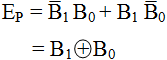
Even Parity
Even parity ensures that the total number of 1s in the data word and the parity bit is even. For example, if the data word is 1001011, the parity bit is 0; if the data word is 1001010, the parity bit is 1. The logic expression for the even parity bit (EP) of a two-bit data word (B1B0) is:

Where ⊕ denotes the XOR operation.
Odd Parity
Odd parity ensures that the total number of 1s in the data word and the parity bit is odd. For example, if the data word is 1001011, the parity bit is 1; if the data word is 1001010, the parity bit is 0. The logic expression for the odd parity bit (OP) of a two-bit data word (B1B0) is:

Where X denotes the complement of X.
What is a Parity Generator?
A parity generator is a combinational logic circuit that generates the parity bit for a given data word at the transmitter end. It takes the original data word as input and outputs the data word with the appended parity bit. Depending on whether even or odd parity is used, different logic gates are required to implement the parity generator.
Even Parity Generator
An even parity generator ensures an even number of 1s in the data word plus the parity bit. If the data word has an odd number of 1s, it adds a 1; if it has an even number of 1s, it adds a 0.
For example, let us design an even parity generator for a three-bit data word (B2B1B0). The truth table and logic expression for the even parity bit (EP) are:
| B2 | B1 | B0 | EP |
|---|---|---|---|
| 0 | 0 | 0 | 0 |
| 0 | 0 | 1 | 1 |
| 0 | 1 | 0 | 1 |
| 0 | 1 | 1 | 0 |
| 1 | 0 | 0 | 1 |
| 1 | 0 | 1 |
| B2 | B1 | B0 | EP |
|---|---|---|---|
| … | … | … | … |
| … | … | … | … |
| … | … | … | … |
| … | … | … | … |
| … | … | … | … |
| … | … | … | … |
| … | … | … | … |
| … | … | … | … |

Odd Parity Generator
An odd parity generator ensures an odd number of 1s in the data word plus the parity bit. If the data word has an odd number of 1s, it adds a 0; if it has an even number of 1s, it adds a 1.
For example, let us design an odd parity generator for a three-bit data word (B2B1B0). The truth table and logic expression for the odd parity bit (OP) are:

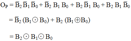
We can implement this expression using two XNOR gates, as shown in Figure below:

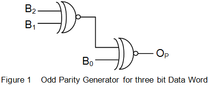
Figure: Three-bit odd parity generator using XNOR gates
Similarly, we can design an odd parity generator for any number of bits by using XNOR gates.
What is a Parity Checker?
A parity checker is a combinational logic circuit that checks the parity of the received data word at the receiver end. It takes the data word with the appended parity bit as input and outputs a signal that indicates whether there is an error or not. Depending on whether even or odd parity is used, different logic gates are required to implement the parity checker.
Even Parity Checker
An even parity checker verifies that the total number of 1s in the received data word with the parity bit is even. If it is even, it outputs a zero signal, indicating no error; if it is odd, it outputs one signal, indicating an error.
For example, let us design an even parity checker for a three-bit data word (B2B1B0) with an even parity bit (EP).

We can implement this expression using three XOR gates.
Similarly, we can design an even parity checker for any number of bits by using XOR gates.
Odd Parity Checker
An odd parity checker verifies that the total number of 1s in the received data word with the parity bit is odd. If it is odd, it outputs a zero signal, indicating no error; if it is even, it outputs one signal, indicating an error.
For example, let us design an odd parity checker for a three-bit data word (B2B1B0) with an odd parity bit (OP). The truth table and logic expression for the error signal (E) are:


We can implement this expression using three XOR gates, as shown in Figure below:

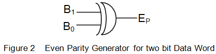
Figure: Three-bit odd parity checker using XOR gates
Similarly, we can design an odd parity checker for any number of bits by using XOR gates.
Applications of Parity Generators and Checkers
Parity generators and checkers are widely used in digital communication and processing systems to detect and correct errors in data transmission and storage. Some examples of applications are:
- Serial Peripheral Interface (SPI) buses use even or odd parities to ensure reliable communication between master and slave devices.
- Universal Asynchronous Receiver Transmitter (UART) transmissions use either no parities or stop bit or two-stop bits to indicate errors or the end of transmission.
- Redundant Array of Independent Disks (RAID) technology uses parties to protect against data loss due to disk failures.
- Hamming codes use parties to correct single-bit errors and detect double-bit errors in binary messages.
- Cyclic Redundancy Check (CRC) codes use parities to detect errors in blocks of binary messages.
Conclusion
Parity generators and checkers are simple but effective devices that help ensure error-free data transmission and processing in digital electronic systems. They use an extra bit, called a parity bit, to detect single-bit errors that may occur due to noise or interference. There are two types of parties: even and odd.


: Basics, Types & Applications")