

- Rogowski Coil Definition: A Rogowski coil is defined as an electrical device that measures alternating current (AC) and high-speed transient or pulsed currents.
- Working Principle: Rogowski coils work based on Faraday’s law, where the voltage induced in the coil is proportional to the current passing through the conductor.
- Core Difference: The key difference between Rogowski coils and AC current transformers is that Rogowski coils use an air core, eliminating magnetic saturation.
- Output and Integration: The voltage output from the coil is connected to an integrator circuit to provide a current signal proportional to the measured current.
- Advantages: Rogowski coils are favored for their ability to handle large currents, low magnetic losses, and simple temperature compensation.
What is a Rogowski Coil?
A Rogowski coil is a non-magnetic-core current sensor for alternating current, pulses and transients within its specified bandwidth and peak rate-of-change limits. It is named after German physicist Walter Rogowski.
Its sensing winding is distributed around a closed loop, with N turns and a controlled cross-section. The core former is non-magnetic, so the sensor does not have an iron-core saturation limit.
A return conductor passes back through the centre of the winding so both terminals are at one end and external-field pickup is reduced.
The loop surrounds the conductor carrying the current to be measured. Conductor position, closure and nearby currents can affect accuracy according to the probe specification.
How does a Rogowski Coil Work?
Under Faraday’s law, the raw coil output is proportional to the time derivative of the enclosed current. Conventional current transformers (CTs) instead provide a secondary current that follows the primary current when operated with the specified burden. The Rogowski voltage therefore needs integration.
A Rogowski sensor uses a non-magnetic core, while a conventional CT uses a high-permeability magnetic core. The non-magnetic design avoids core saturation but generally has lower raw sensitivity.
A changing conductor current produces changing magnetic flux through the sensing winding, which induces a terminal voltage.
The raw voltage is proportional to dI/dt, not directly to current. An integrator circuit reconstructs a voltage proportional to current over the probe’s stated bandwidth.
Rogowski Coil Current Sensor
The non-magnetic core eliminates saturation and hysteresis in the sensing head and gives low insertion impedance. The winding and integrator still have thermal, voltage, bandwidth and noise limits.
Rogowski probes are useful for large AC currents and fast transients when their current range, dI/dt limit and bandwidth match the measurement.
The non-magnetic toroidal winding does not saturate like an iron core, but excessive dI/dt can overdrive or damage the coil termination or integrator.
Measurement and protection versions cover different ranges. The coil converts dI/dt to voltage; the integrator converts that signal to an output proportional to current.
Mechanical forms include rigid and flexible heads, with passive or active integration and different accuracy classes.
Rogowski Coil Design
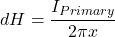
Consider the conductive element ‘dr’ at distance ‘x’ from the origin. The current-carrying conductor is placed at the center of the coil. The figure below shows the arrangement of a typical Rogowski coil.

For the ideal centred, infinitely long straight conductor assumed here, the biot-savart law gives magnetic-field strength at radius x. The protected equation uses dH, although H is the field value rather than a differential:
(1) 
The magnetic flux density at point ‘dr’ is
(2) 
Here μ is approximately the permeability of free space for a non-magnetic former.
From the above equations, the magnetic flux density due to a current flowing through the conductor is
(3) 
The magnetic flux is given as
(4) 
Where dA is rectangular cross-section area for element ‘dr’ and that is given as
![\[ dA = dr \times h \]](https://www.staging.electrical4u.com/wp-content/ql-cache/quicklatex.com-29ee89127e4caf0c84c0abc53ac0476d_l3.png "Rendered by QuickLaTeX.com")
(5) 
![\[ \phi = \mu \times \frac{I_{Primary}}{2 \pi } \times h \times \int_{a}^{b} \frac{1}{x} dr \]](https://www.staging.electrical4u.com/wp-content/ql-cache/quicklatex.com-90909a2a1f1f50c97188c55d182b0c17_l3.png "Rendered by QuickLaTeX.com")
Therefore, total flux is
(6) 
![\[ \frac{d\phi}{dt} = \frac { \mu \times h}{2 \pi } \times \ln \frac{b}{a} \times \frac{dI_{Primary}}{dt } \]](https://www.staging.electrical4u.com/wp-content/ql-cache/quicklatex.com-a1fed4756d66e65915d7697a5ca25f9f_l3.png "Rendered by QuickLaTeX.com")
Under Lenz’s law, induced voltage has a polarity that opposes the flux change. The protected expressions below omit the minus sign, so their sign depends on the chosen terminal reference:
(7) 
(8)
(9) 
The mutual inductance M is the coefficient multiplying dI/dt. The protected expression below is incomplete because it ends with a multiplication sign; for this ideal geometry, remove that trailing sign.
(10) 
Now, assume that sinusoidal current flowing through the conductor with an amplitude ‘Im’ and frequency ‘f’.
So, the voltage induced in the Rogowski coil is given by
(11) 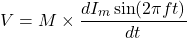
(12) 
At time t=0, the magnitude of voltage is maximum. So, the peak voltage is given as;
(13) 
RMS value of the voltage;
(14) 
For a sine wave, raw RMS coil voltage is M × 2πf × RMS current. The protected 4.44 expression above is incorrect for a Rogowski derivative output. The 4.44 factor belongs to the transformer sinusoidal EMF relation written with maximum flux, not RMS current.
Rogowski Coil Integrator
An ideal integrator introduces a -90° phase shift. Real circuits have low- and high-frequency limits, gain error, phase error, drift and noise. Component choice and calibration control these errors only within a stated bandwidth.
Common implementations are:
- Passive Integrator
- Active Integrator
Passive Integrator
For a large output range of Rogowski coils, the series RC circuit act as an integrator. The value of the acceptable phase error decides the value of Resistance (R) and Capacitance (C).
The relationship between R and C and phase error can be derived from the phasor diagram of the RC network. And it is as shown in the below figure.

In the phasor diagram:
VR and VC are the resistor and capacitor voltages;
IT is the series current;
V0 is the output across capacitor VC;
VIN is the vector sum of the resistor and capacitor voltages.
The voltage drop across the resistor is in-phase and a voltage drop across the capacitor will lag by 90˚ with respect to the net current.
The phase angle between VIN and V0 is known as the phase difference between the integrator’s input and output and this angle should be close to 90˚.
The deviation between the actual phase angle and ideal phase angle is phase error and it is represented by ф.
If we increase the drop across the resistor (VR’), the phase will decrease.
The value of R and C can be estimated by the below equations.
![\[\tan(\phi) = \frac{X_c}{R} \]](https://www.staging.electrical4u.com/wp-content/ql-cache/quicklatex.com-4c89516fee5cf1a017442a6bc6127a9f_l3.png "Rendered by QuickLaTeX.com")
![\[ X_c = \frac{1}{2 \pi f C} \]](https://www.staging.electrical4u.com/wp-content/ql-cache/quicklatex.com-288f30f8a5bf1e560ad76ae52473111a_l3.png "Rendered by QuickLaTeX.com")
![\[ \tan(\phi) = \frac{1}{2 \pi f C R} \]](https://www.staging.electrical4u.com/wp-content/ql-cache/quicklatex.com-66086b0c946edff81f00aec0bc8d8f49_l3.png "Rendered by QuickLaTeX.com")
![\[ RC = \frac{1}{2 \pi f \tan(\phi)} \]](https://www.staging.electrical4u.com/wp-content/ql-cache/quicklatex.com-39ee49213d86d7d8608296cf3c4e74cc_l3.png "Rendered by QuickLaTeX.com")
Where,
Ф = Target phase error
XC = Capacitive Impedance
R = Resistance
f = Input Frequency
In this equation, assume the value of R or C and find the value of the remaining element.
Active Integrator
The RC circuit acts as an attenuator, reducing the voltage across the capacitor. At low current levels, the output voltage can be very low, in microvolts (μV), creating a weak signal for the Analog to Digital Converter (ADC).
This problem can be solved by using an Active Integrator. The circuit of an active integrator is as shown in the below figure.

Here, the RC element is in a feedback path of an Amplifier. The gain of the amplifier can be adjusted by using the below equation.
![\[ Gain = \frac{VOUT_{MAX} - VOUT_{MIN}}{VIN_{MAX} - VIN_{MIN}} \]](https://www.staging.electrical4u.com/wp-content/ql-cache/quicklatex.com-75fe8e1cab38c7adad0861890bb438a2_l3.png "Rendered by QuickLaTeX.com")
![\[ Gain = - \frac{R_F || X_C}{R_1} \]](https://www.staging.electrical4u.com/wp-content/ql-cache/quicklatex.com-1927282c34c42aca6b2968f708e23a09_l3.png "Rendered by QuickLaTeX.com")
Advantages of Rogowski Coil
The advantages of Rogowski coils include:
- It can respond to fast-changing currents.
- The coil is a voltage-output sensor and does not have the dangerous open-secondary behaviour of an energised conventional CT.
- The non-magnetic core does not saturate.
- Temperature compensation can be implemented, but the winding and integrator coefficients still require specification.
- A flexible head can fit around large or awkward conductors without the heavy magnetic core of a comparable high-current CT.
- It is available in two types; flexible as well as rigid.
Disadvantages of Rogowski Coil
The disadvantages of Rogowski coils include:
- The raw output needs integration. Active integrators require a product-specific power supply; passive integrators do not.
- It cannot measure steady DC current because dI/dt is zero.


