

- Electrical Impedance Definition: Electrical impedance is defined as the measure of opposition that a circuit presents to a current when a voltage is applied, involving both resistance and reactance.
- Impedance vs. Resistance: Unlike resistance, impedance varies with the frequency of the applied voltage and has both magnitude and phase.
- Reactance Effects: In an inductive circuit, current lags the voltage by 90 degrees, while in a capacitive circuit, current leads the voltage by 90 degrees.
- Series and Parallel Circuits: Impedance in series and parallel RL and RC circuits can be calculated using specific formulas that combine resistance and reactance.
- Practical Applications: Understanding impedance is crucial for designing and analyzing circuits in AC systems where both resistance and reactance affect performance.
What is Electrical Impedance?
In electrical engineering, electrical impedance is the measure of the opposition that a circuit presents to a current when a voltage is applied. Impedance extends the concept of resistance to alternating current (AC) circuits. Impedance possesses both magnitude and phase, unlike resistance, which has only magnitude.
Unlike electrical resistance, the opposition of electrical impedance to current depends on the circuit’s frequency. Resistance can be seen as impedance with a phase angle of zero.
In a purely inductive circuit, the current lags the applied voltage by 90 degrees. In a purely capacitive circuit, the current leads the voltage by 90 degrees. In a purely resistive circuit, the current neither lags nor leads the voltage. When a circuit is powered by direct current (DC), impedance and resistance are the same.
In practical circuits with both inductive reactance and capacitive reactance along with resistance, or with either reactance type and resistance, the current will lead or lag based on the values of reactance and resistance.
In an AC circuit, the combined effect of reactance and resistance is called impedance, usually denoted by the letter Z. The value of impedance is represented as:
Where R is the value of circuit resistance and X is the value of circuit reactance.
The angle between applied voltage and current is
The inductive reactance is taken as positive and capacitive reactance is taken as negative.
Impedance can be represented in complex form. This is
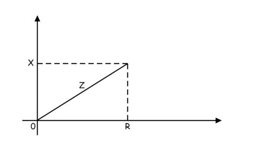
The real part of a complex impedance is resistance and the imaginary part is reactance of the circuit.
Let us apply a sinusoidal voltage Vsinωt across a pure inductor of inductance L Henry.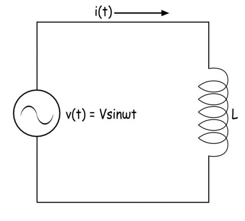
The expression of current through the inductor is
From the expression of the waveform of the current through the inductor it is clear that the current lags the applied voltage by 90° (electrical).
Now let us apply same sinusoidal voltage Vsinωt across a pure capacitor of capacitance C farad.
The expression of current through the capacitor is
From the expression of the waveform of the current through the capacitor it is clear that the current leads the applied voltage by 90°(electrical).
Now we will connect the same voltage source across a pure resistance of value R ohm.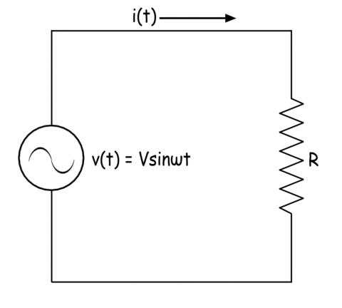
Here the expression of current through the resistance would be
From that expression, it can be concluded that the current has the same phase with the applied voltage.
Impedance of a Series RL Circuit
Let us derive the expression of the impedance of a series RL circuit. Here resistance of value R and inductance of value L are connected in series. The value of reactance of the inductor is ωL. Hence the expression of impedance in complex form is
The numerical value or mod value of the reactance is
Impedance of a Series RC Circuit
Let us connect one resistance of value R ohm in series with a capacitor of capacitance C farad. The reactance of the capacitor is 1 / ωC. The resistance R and reactance of the capacitor are in series the expression of the impedance can be written as
The mod value of the impedance of the series RC circuit is
Impedance of a Parallel RL Circuit
Here the resistance and inductor are connected in parallel. Here reciprocal of the impedance of the circuit is the sum of the reciprocal of resistance and reciprocal of reactance.
The expression of the impedance of the parallel RL circuit can be represented as
Impedance of a Parallel RC Circuit
Here as the capacitor and resistor are connected in parallel, the reciprocal of the impedance of the circuit is the sum of the reciprocal of resistance and reciprocal of the reactance of the capacitor.
Finally, we can write the expression of the impedance of the parallel RC circuit as
Impedance of a Series RLC Circuit
Here resistors, capacitors, and inductors are connected in series. The total reactance of the circuit is the sum of the reactance of inductors and capacitors. The reactance of the capacitors is taken as negative. The expression of impedance of a series RLC circuit is
Impedance of a Parallel RLC Circuit
Here resistor, capacitor, and inductor are connected in parallel. In the same way, the equivalent impedance of a parallel RLC circuit can be determined and the finally the expression of the impedance of a parallel RLC circuit is
Polar Representation of Impedance

")
")
