

- Analog to Digital Converter Definition: An Analog to Digital Converter (ADC) is a device that changes a continuous analog signal into a discrete digital signal.
- ADC Process: The conversion process involves Sampling and Holding, and Quantizing and Encoding.
- Quantizing and Encoding in ADC: Quantizing divides the signal into levels, and Encoding assigns digital codes to these levels.
- Improving ADC Accuracy: Accuracy can be improved by increasing the resolution and the sampling rate.
- Types and Applications of ADCs: ADCs include types like Successive Approximation and Flash ADCs and are used in various devices like computers and cell phones.
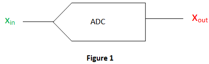
From the name itself it is clear that it is a converter which converts the analog (continuously variable) signal to digital signal. This is really an electronic integrated circuit which directly converts the continuous form of signal to discrete form. It can be expressed as A/D or A-to-D or A-D or ADC. The input (analog) to this system can have any value in a range and are directly measured. But for output (digital) of an N-bit A/D converter, it should have only 2N discrete values. This A/D converter is a linkage between the analog (linear) world of transducers and discreet world of processing the signal and handling the data. The digital to analog converter (DAC) carry out the inverse function of the ADC. The schematic representation of ADC is shown below.
ADC Process
There are mainly two steps involves in the process of conversion. They are
- Sampling and Holding
- Quantizing and Encoding
The whole ADC conversion process is shown in figure 2.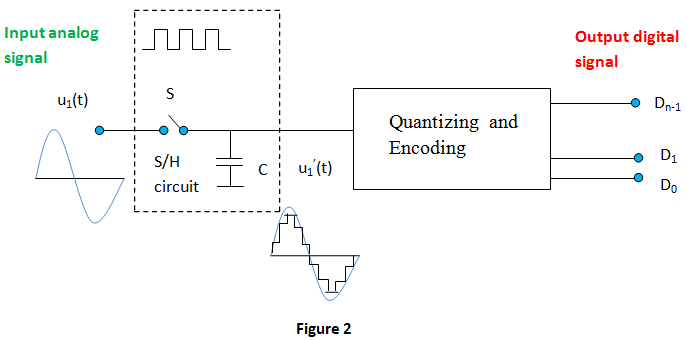
Sampling and Holding
In Sampling and Holding (S/H), the continuous signal is sampled and held steady for a short period. This removes variations in the input signal that could affect conversion accuracy. The minimum sampling rate must be twice the maximum frequency of the input signal.
Quantizing and Encoding
For understanding quantizing, we can first go through the term Resolution used in ADC. It is the smallest variation in analog signal that will result in a variation in the digital output. This actually represents the quantization error.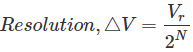
V → Reference voltage range
2N → Number of states
N → Number of bits in digital output
Quantizing is the process of dividing the reference signal into several discrete levels, or quanta, and then matching the input signal to the correct level.
Encoding assigns a unique digital code to each discrete level (quantum) of the input signal. The process of quantizing and encoding is demonstrated in the table below.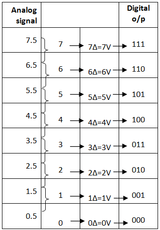
From the above table we can observe that only one digital value is used to represent the whole range of voltage in an interval. Thus, an error will occur and it is called quantization error. This is the noise introduced by the process of quantization. Here the maximum quantization error is 
Improvement of Accuracy in ADC
To improve ADC accuracy, two methods are commonly used: increasing the resolution and increasing the sampling rate. This is shown in figure below (figure 3).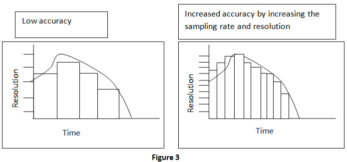
Types of Analog to Digital Converter
- Successive Approximation ADC: This converter compares the input signal with the output of an internal DAC at each successive step. It is the most expensive type.
- Dual Slope ADC: It have high accuracy but very slow in operation.
- Pipeline ADC: It is same as that of two step Flash ADC.
- Delta-Sigma ADC: It has high resolution but slow due to over sampling.
- Flash ADC: It is the fastest ADC but very expensive.
- Other: Staircase ramp, Voltage-to-Frequency, Switched capacitor, tracking, Charge balancing, and resolver.
Application of ADC
- Used together with the transducer.
- Used in computer to convert the analog signal to digital signal.
- Used in cell phones.
- Used in microcontrollers.
- Used in digital signal processing.
- Used in digital storage oscilloscopes.
- Used in scientific instruments.
- Used in music reproduction technology etc.

")

