
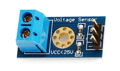
- Voltage Sensor Definition: A voltage sensor is a device that measures voltage in an object, handling both AC and DC types.
- Working Principle: Voltage sensors function by converting the input voltage into a variety of outputs such as analog signals or audible alerts.
- Types of Voltage Sensors: There are mainly two types—capacitive and resistive, each suited for different applications and characteristics.
- Circuit Diagram Insights: Understanding circuit diagrams of voltage sensors helps in grasping how they function and are connected.
- Practical Applications: Voltage sensors are essential in electronics for detecting power issues and ensuring safe operations.
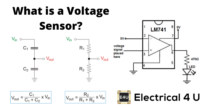
What is a Voltage Sensor?
A voltage sensor measures and monitors voltage levels within an object, detecting either AC or DC voltage. It inputs voltage and outputs various forms such as switches, analog voltage signals, current signals, or audible signals.
Sensors are devices that can sense or identify and react to certain types of electrical or optical signals. The implementation of a voltage sensor and current sensor techniques have become an excellent choice for the conventional current and voltage measurement methods.
Types of Voltage Sensors
In this article, we can discuss a voltage sensor in detail. A voltage sensor can determine, monitor, and measure the supply of voltage. It can measure the AC level and/or DC voltage level. The input to the voltage sensor is the voltage itself, and the output can be analog voltage signals, switches, audible signals, analog current levels, frequency, or even frequency-modulated outputs.
That is, some voltage sensors can provide sine or pulse trains as output, and others can produce amplitude modulation, pulse width modulation, or frequency modulation outputs.
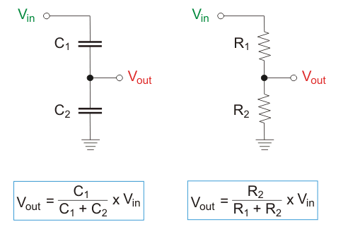
In voltage sensors, the measurement is based on a voltage divider. Two main types of voltage sensors are available: capacitive type voltage sensor and resistive type voltage sensor.
Capacitive Voltage Sensor
A capacitor consists of two conductors, known as plates, separated by a non-conductive material.
This non-conductive material, called a dielectric, allows current to flow across the plates when an AC voltage is applied, driven by the movement of electrons toward or away from the opposite plate.
The field among the plates will create a complete AC circuit without any hardware connection. This is how a capacitor works.
Next, we can discuss the voltage division in two capacitors which are in series. Usually, in series circuits, high voltage will develop across the component with high impedance. In the case of capacitors, capacitance and impedance (capacitive reactance) are always inversely proportional.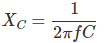
The relation between voltage and capacitance is

Q → Charge (Coulomb)
C → Capacitance (Farad)
XC → Capacitive reactance (Ω)
f → Frequency (Hertz)
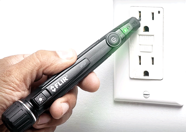
From the above two relations, we can clearly state that the highest voltage will accumulate across the smallest capacitor. The capacitor voltage sensors work based on this simple principle. Consider we are holding the sensor and then placing its tip near a live conductor.
Here, we are inserting the sensing element of high impedance into a series capacitive coupling circuit.
Presently, the sensor’s tip is the smallest capacitor coupled to the live voltage. Thus, the whole voltage will develop across the sensing circuit, which can detect voltage, and the light or buzzer indicator is turned on—this is behind the non-contact voltage sensors you use at home.
Resistive Voltage Sensor
Two ways exist to convert the resistance of the sensing element to the voltage. The first one is the simplest method, which is to provide a voltage to the resistor divider circuit comprised of a sensor and a reference resistor, which is represented below.
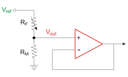
The voltage across the reference resistor or sensor is buffered before being sent to the amplifier. The output voltage from the sensor can be calculated as follows:
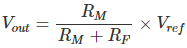
A drawback of this circuit is that the amplifier amplifies the entire voltage across the sensor. A more effective approach is to amplify only the voltage changes caused by resistance changes in the sensor, achieved using a resistance bridge.
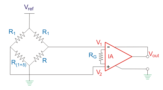
Here, the output voltage is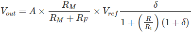
When R1 = R, then the output voltage becomes approximately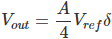
A → Gain of instrumentation amplifier
δ → Change in the resistance of the sensor, which is analogous to some physical action
In this equation, the gain must be set high because only the voltage change due to the change in the sensor’s resistance is being amplified.
Advantages of Voltage Sensors Over Conventional Measuring Techniques
The advantage of voltage sensors include:
- Small in weight and size
- Personnel safety is high
- The degree of accuracy is very high
- Non-saturable
- Wide dynamic range
- Eco-friendly
Can combine the voltage and current measurement into a single physical device with small and compact dimensions
Applications of Voltage Sensors
The application of voltage sensors include the following:
- Power failure detection
- Load sensing
- Safety switching
- Temperature control
- Power demand control
- Fault detection
Voltage sensors are included in many of the best Arduino starter kits, as they are very useful in many electronics projects.


