
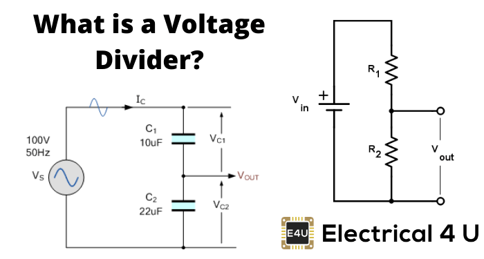
- Voltage Divider Definition: A voltage divider is a simple circuit that creates a part of its input voltage as output, using two resistors in series.
- Circuit Components: The circuit includes two resistors connected in series with a voltage source, splitting the input voltage.
- Unloaded Equation: With no current flowing out, the output voltage depends on the ratio of the resistors.
- Loaded Condition: Adding a load resistor changes the output voltage calculation because of the parallel resistance.
- Applications: Voltage dividers are used for logic level shifting, sensor measurement, and reducing high voltages for safe measurement.
What is a Voltage Divider?
A voltage divider is a fundamental circuit in the field of electronics which can produce a portion of its input voltage as an output. It is formed using two resistors (or any passive components) and a voltage source. The resistors are connected in series here and the voltage is given across these two resistors.
This circuit is also called a potential divider. The input voltage is shared among the resistors, resulting in voltage division. For help with voltage division calculations, you can use our voltage divider calculator.
Circuit of Voltage Divider
As we mentioned above, two series resistors and voltage source constitute a simple voltage divider. This circuit can be formed in several ways as shown below.
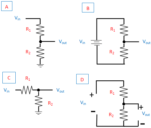
In the figure, (A) shows the shorthand version, (B) the longhand version, and (C) and (D) depict the resistors at different and same angles.
But all the four circuits are in effect the same. R1 is the resistor that is always close to the input voltage source and R2 is the resistor that is near to the ground. Vout is the voltage drop across the resistor, R2.
It is actually the divider voltage that we get from this circuit as the output.
Equation of Voltage Divider in Unloaded Condition
The simple voltage divider circuit with reference to the ground is shown below. It has two electrical impedances (Z1 and Z2) or any passive components connected in series. These impedances can be resistors, inductors, or capacitors.
The output of the circuit is taken across the impedance, Z2.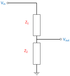
Under open-circuit output condition; that is there will be no current flow in the output side, then
Now we can prove the output voltage equation (1) using the basic law, Ohm’s Law
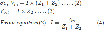
Substitute equation (4) in (3), we get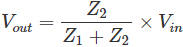
So, the equation is proved.
The transfer function of the above equation is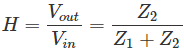
This equation is also called as Divider’s
The capacitive divider circuits never allow DC input to pass. They work on AC input.
For an Inductive divider with non-interacting inductors, the equation becomes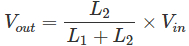
The inductive divider divides the DC input analogous to resistor divider circuit depending on resistance and it divides AC input with regard to the inductance.
A basic low-pass RC filter circuit is shown below which comprises of a resistor and capacitor.

C → Capacitance
R → Resistance
XC → Reactance of the capacitor
ω → Radiant frequency
j → Imaginary unit
Here, the divider’s voltage ratio is
RC → Time constant of the circuit represented as τ.
Voltage Divider Under Loaded Condition
Now, we can see the voltage divider circuit in a loaded condition. Here, the resistors (R1 and R2) are taken for simplicity. A resistor (RL) is connected across the output. Then the equation becomes,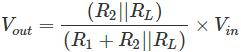
R2 and RL are parallel to each other.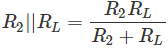
The circuit with the loaded condition is shown below.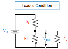
Applications of Voltage Divider
Applications include Logic level shifting, Sensor measurement, High voltage measurement, Signal Level Adjustment.
The measuring instruments such as Multimeter and Wheatstone bridge consist of the voltage divider.
The resistor voltage divider is often used to create reference voltages or to reduce voltage magnitude for easier measurement.
In addition to this; at low frequency, it can function as signal attenuators.
In the case of DC and very low frequencies, the resistor voltage divider is suitable. The capacitive voltage divider is implemented in power transmission for high voltage measurement and to compensate load capacitance.


