
- DC Circuit Definition: A DC circuit is defined as an electrical circuit that handles direct current, where the current flows in one direction.
- Series DC Circuit: In a series DC circuit, all components are connected end to end, allowing the same current to flow through each component.
- Voltage Drops in Series: The voltage drop across each component in a series DC circuit is proportional to its resistance.
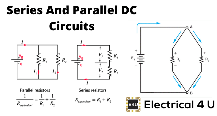
- Parallel DC Circuit: A parallel DC circuit has components connected across common points, providing the same voltage drop across each component.
- Current Distribution in Parallel: In a parallel DC circuit, the total current is divided among the parallel paths, with each path’s current inversely proportional to its resistance.
What is an Electrical Circuit?
An electrical circuit is a setup of two or more electrical components connected by paths that conduct electricity. These components can be active components, or inactive components, or a mix of both.
What is a DC Circuit?
There are two types of electricity: direct current (DC) and alternating current (AC). A circuit that handles DC is called a DC circuit, while one that handles AC is known as an AC circuit.
The components of the electrical DC circuit are mainly resistive, whereas components of the AC circuit may be reactive as well as resistive.
Any electrical circuit can be categorized into three different groups – series, parallel, and series-parallel. So for example, in the case of DC, the circuits can also be divided into three groups, such as series DC circuit, parallel DC circuit, and series and parallel circuit.
What is a Series DC Circuit?
A series DC circuit is when all resistive components are connected end to end, forming a single path for current flow. This end-to-end connection is called a series connection.
Suppose we have n number of resistors R1, R2, R3………… Rn and they are connected in an end to end manner, which means they are series-connected. If this series combination is connected across a voltage source, the current starts flowing through that single path.
As the resistors are connected in the end to end manner, the current first enters into R1, then this same current comes in R2, then R3 and at last it reaches Rn from which the current enters into the negative terminals of the voltage source.
In this way, the same current circulates through every resistor connected in series. Hence, it can be concluded that in a series DC circuit, the same current flows through all parts of the electrical circuit.
Again according to Ohm’s law, the voltage drop across a resistor is the product of its electrical resistance and the current flow through it.
Here, the current through every resistor is the same, hence the voltage drop across each resistor’s proportional to its electrical resistance value.
If the resistances of the resistors are not equal then the voltage drop across them would also not be equal. Thus, every resistor has its individual voltage drop in a series DC circuit.
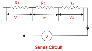
Electrical DC Series Circuit with Three Resistors
Below is a figure of a DC series circuit with three resistors. The flow of current is shown here by a moving point. Note that this is just a conceptual representation.

Series DC Circuit Example
Suppose three resistors R1, R2, and R3 are connected in series across a voltage source of V (quantified as volts) as shown in the figure. Let current I (quantified as Ampere) flow through the series circuit. Now according to Ohm’s law,
The voltage drop across resistor R1, V1 = IR1
The voltage drop across resistor R2, V2 = IR2
The voltage drop across resistor R3, V3 = IR3
The voltage drop across the whole series DC circuit,
V = Voltage drop across resistor R1 + voltage drop across resistor R2 + voltage drop across resistor R3

According to Ohm’s law, the electrical resistance of an electrical circuit is given by V ⁄ I and that is R. Therefore,
So, the effective resistance of the series DC circuit is  . From the above expression it can be concluded, that when a number of resistors are connected in series, the equivalent resistance of the series combination is the arithmetic sum of their individual resistances.
From the above discussion, the following points come out:
- When a number of electrical components are connected in series, the same current flows through all the components of the circuit.
- The applied voltage across a series circuit is equal to the sum total of voltage drops across each component.
- The voltage drop across individual components is directly proportional to its resistance value.
What is a Parallel DC Circuit?
In a parallel DC circuit, two or more components are connected so that one end of each component meets at a common point and the other end at another common point. This setup allows multiple paths for current flow.
In this circuit, every component will have the same voltage drop across them, and it will be exactly equal to the voltage which occurs between the two common points where the components are connected.
Also in a parallel DC circuit, the current has several parallel paths through these parallel-connected components, so the circuit current will be divided into as many paths as the number of components.
Here, in this electrical circuit, the voltage drop across each component is equal. Again as per Ohm’s law, the voltage drop across any resistive component is equal to the product of its electrical resistance and current through it.
As the voltage drop across every component connected in parallel is the same, the current through them is inversely proportional to its resistance value.
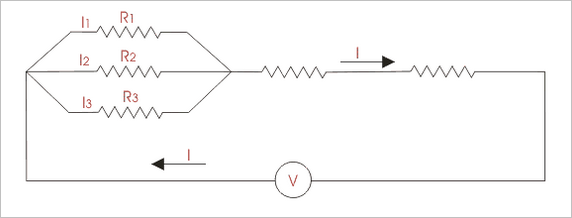
Electrical DC Parallel Circuit with Three Resistors
The image below shows a DC parallel circuit with three resistors. The current flow is represented by a moving point. This is a conceptual illustration.

Parallel DC Circuit Examples
Suppose three resistors R1, R2, and R3 are connected in parallel across a voltage source of V (volt) as shown in the figure. Let I (Ampere) be the total circuit current which is divided into current I1, I2, and I3 flowing through R1, R2, and R3 respectively. Now according to Ohm’s law:
The voltage drop across resistor R1, V = I1.R1
The voltage drop across resistor R2, V = I2.R2
The voltage drop across resistor R3, V = I3.R3
The voltage drop across the whole parallel DC circuit,
V = Voltage drop across resistor R1 = voltage drop across resistor R2 = voltage drop across resistor R3
⇒ V = I1.R1 = I2.R2 = I3.R3

Thus when a number of resistors are connected in parallel, the reciprocal of the equivalent resistance is given by the arithmetic sum of the reciprocals of their individual resistances.
From the above discussion of the parallel DC circuit, we can come to the following conclusion:
- Voltage drops are the same across all the components connected in parallel.
- Current through individual components connected in parallel is inversely proportional to their resistances.
- Total circuit current is the arithmetic sum of the currents passing through individual components connected in parallel.
- The reciprocal of equivalent resistance is equal to the sum of the reciprocals of the resistances of individual components connected in parallel.
Series and Parallel Circuits Combined
So far we have discussed series DC circuits and parallel DC circuits separately, but in practice, the electrical circuit is generally a combination of both series circuits and parallel circuits.
Such combined series and parallel circuits can be solved by proper application of Ohm’s law and the rules for series and parallel circuits to the various parts of the complex circuit.
Series and Parallel Circuit

")

