

- Voltage Controlled Oscillator Definition: A voltage controlled oscillator (VCO) is defined as an oscillator whose output frequency is controlled by an input voltage.
- Frequency Control Mechanism: The frequency of a VCO is directly proportional to the control voltage, meaning as the input voltage increases, the frequency increases.
- Types of VCOs: VCOs can be harmonic oscillators, which produce sinusoidal waveforms, or relaxation oscillators, which produce sawtooth waveforms.
- Op-amp Based VCO: In a VCO circuit using Op-amps, the first Op-amp functions as an integrator and the second as a Schmitt trigger to produce square and triangular waveforms.
- Applications of VCO: Voltage controlled oscillators are used in function generators, phase-locked loops, tone generators, frequency-shift keying, and frequency modulation.
A voltage controlled oscillator (VCO) is defined as an oscillator whose output frequency is controlled by an input voltage. It can produce a wide range of frequencies, from a few Hertz to hundreds of Giga Hertz, based on the input DC voltage.
Frequency Control in Voltage Controlled Oscillator
VCOs take many forms: RC, multivibrator, LC or crystal oscillator types. In an RC oscillator, the output oscillation frequency is inversely proportional to the capacitance:

In an LC oscillator, the output oscillation frequency is 
Raising the input (control) voltage therefore reduces the capacitance, so the control voltage and the oscillation frequency are directly proportional: when one rises, the other follows.
The figure above shows the basic behaviour of a voltage controlled oscillator. At the nominal control voltage VC(nom), the oscillator runs at its free-running frequency fC(nom). Lowering the control voltage below nominal lowers the frequency; raising it raises the frequency.
Varactors diodes, variable-capacitance diodes available in different ranges, provide this voltage-controlled capacitance. In low-frequency oscillators, a voltage-controlled current source changes the charging rate of the capacitors.
Types of Voltage Controlled Oscillator
The VCOs can be categorized based on the output waveform:
- Harmonic Oscillators
- Relaxation Oscillators
Harmonic Oscillators
Harmonic oscillators produce a sinusoidal output, so this type is often called a linear voltage controlled oscillator. Examples are LC and Crystal oscillators. The capacitance of the varactor diode changes with the voltage across the diode, which in turn alters the LC circuit’s capacitance and changes the output frequency. Advantages include frequency stability against supply, noise and temperature variations, plus accurate frequency control. The main drawback is that this oscillator type is difficult to implement on monolithic ICs.
Relaxation Oscillators
Relaxation oscillators produce a saw-tooth output. This type covers a wide frequency range with few components and suits monolithic IC implementation well. Relaxation oscillators use the following topologies:
- Delay-based ring VCOs
- Grounded capacitor VCOs
- Emitter-Coupled VCOs
In delay-based ring VCOs, gain stages connect in a ring, and the frequency follows the delay of each stage. The grounded-capacitor and emitter-coupled types work almost alike: each stage period relates directly to the charging and discharging time of the capacitor.
Working Principle of Voltage Controlled Oscillator (VCO)
VCO circuits can be designed by means of many voltage control electronic components such as varactor diodes, transistors, Op-amps etc. Here, we are going to discuss about the working of a VCO using Op-amps. The circuit diagram is shown below.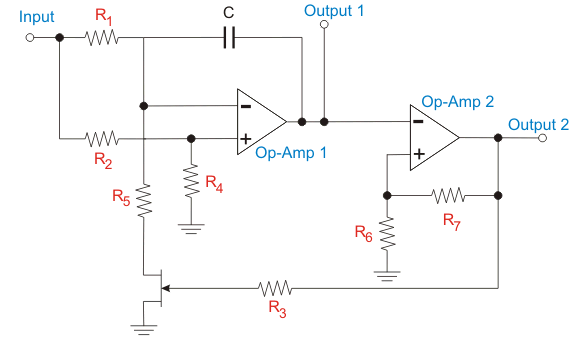
The output waveform of this VCO will be square wave. As we know the output frequency is related to the control voltage. In this circuit the first Op-amp will function as an integrator. The voltage divider arrangement is implemented here. Because of this, the half of the control voltage that is given as input is given to the positive terminal of the Op-amp 1. The same level of voltage is maintained at the negative terminal. This is to sustain the voltage drop across the resistor, R1 as half of the control voltage.
When the MOSFET is in on condition, the current flowing from the R1 resistor passes through the MOSFET. The R2 have half the resistance, same voltage drop and twice the current as that of R1. So, the extra current charges the connected capacitor. The Op-amp 1 should provide a gradually increasing output voltage to supply this current.
With the MOSFET off, the current from R1 resistor passes through the capacitor and discharges it, so the output voltage of Op-amp 1 falls. The result is a triangular waveform at the output of Op-amp 1.
The second Op-amp works as a Schmitt trigger on that triangular wave. When its input voltage exceeds the threshold, the output switches to VCC; below the threshold it drops to zero, giving the square-wave output.
A classic example is the LM566, or IC 566: an 8-pin integrated circuit that delivers two outputs, a square wave and a triangular wave. The internal circuit is represented below.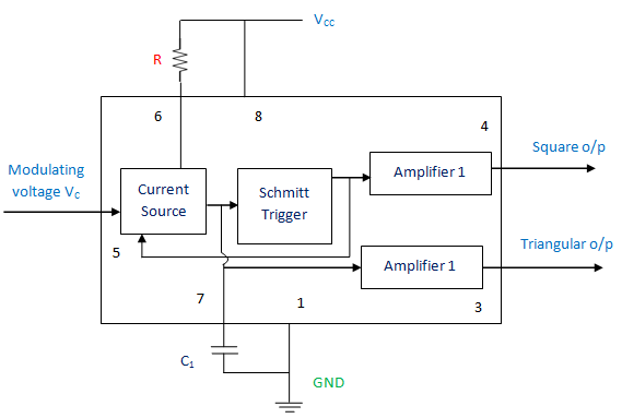
Applications of Voltage Controlled Oscillator
- Function generator
- Phase Locked Loop
- Tone generator
- Frequency-shift keying
- Frequency modulation


