- Polarity Test Definition: A polarity test of transformer is a method to ensure correct polarity alignment when connecting transformers in parallel.
- Dot Convention: The dot convention identifies the polarity of windings in a transformer, showing how voltage is induced.
- Additive Polarity: In additive polarity, the voltage between primary and secondary windings adds up, used in small transformers.
- Subtractive Polarity: In subtractive polarity, the voltage between primary and secondary windings is the difference, used in large transformers.
- Testing Procedure: The polarity test involves using voltmeters to check if the voltages add or subtract correctly, ensuring proper connection.
A polarity test of a transformer finds whether the two windings add or subtract when a jumper joins adjacent terminals. Current in each winding follows the terminal voltage and the potential difference across that winding. The test uses those AC voltages, not battery polarity on a DC pair of terminals.
Dot convention marks the voltage polarity of the mutual inductance of two windings. The two used conventions are:
- If a current enters the dotted terminal of one winding, then the voltage induced on the other winding will be positive at the dotted terminal of the second winding.
- If a current leaves the dotted terminal of one winding, then the polarity of the voltage induced in the other winding will be negative at the dotted terminal of the second winding.
Distribution transformers are often paralleled for extra capacity or backup. Matching polarity is a condition of that transformers in parallel connection.
Paralleling joins corresponding primary terminals of the same polarity, then the matching secondary terminals. That raises capacity and can add a spare unit.
A polarity test is done on each transformers unit before paralleling, so same-polarity terminals are joined. Opposite polarity on the bus drives a heavy circulating current and can damage the transformer.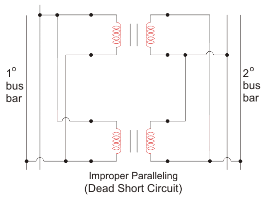
Polarity of the transformer is grouped as two types,
- Additive Polarity
- Subtractive Polarity

Additive Polarity
In additive polarity, the voltage (Vc) between the remaining primary terminal (Va) and secondary terminal (Vb) is the sum of the two winding voltages: Vc = Va + Vb
Subtractive Polarity
In subtractive polarity, the voltage (Vc) between the remaining primary terminal (Va) and secondary terminal (Vb) is the difference of the two winding voltages: Vc = Va – Vb
A subtractive reading Vc = Va – Vb does not identify a step-down transformer. Comparing Vc with Vb – Va still does not identify a step-up transformer. Voltage ratio on the nameplate does that.
ANSI distribution practice often uses additive polarity on smaller distribution transformers and subtractive polarity on larger power transformers. IEC 60076 terminal marking is a subtractive-style convention. Check the nameplate and the applicable standard.
Procedure of Polarity Test of Transformer
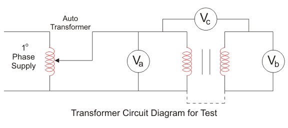
- Connect the circuit as shown above with a voltmeter (Va) across primary winding and another voltmeter (Vb) across the secondary winding.
- If available, take down the ratings of the transformer and the turn ratio.
- We connect a voltmeter (Vc) between primary and secondary windings.
- We apply some voltage to the primary side.
- By checking the value in the voltmeter (Vc), we can find whether it is additive or subtractive polarity.
If additive polarity, Vc shows the sum of Va and Vb.
If subtractive polarity, Vc shows the difference between Va and Vb.
Caution: The Vc voltmeter must be rated above Va + Vb (primary plus secondary). On additive polarity the sum of Va and Vb appears across it.
Note: If additive polarity is needed but the unit is subtractive, reverse one winding’s connections and leave the other as is. The same swap works the other way.