

- Heaviside Bridge Definition: The Heaviside bridge circuit is defined as a bridge circuit that measures mutual inductance using four non-inductive resistors and an unknown mutual inductor.
- Uses of Mutual Inductor: Mutual inductors are used in bridge circuits to find the value of unknown mutual inductance and self-inductance in various circuits.
- Mathematical Derivation: The mutual inductance of two coils in series is calculated by finding the difference between the self-inductances when fields are additive and when reversed.
- Heaviside Bridge Applications: The main application of the Heaviside bridge is to measure mutual inductance in terms of self-inductance in industrial settings.
- Modified Heaviside Bridge: Campbell’s modified Heaviside bridge includes a balancing coil and resistor to measure unknown self-inductance more accurately.
Before introducing the Heaviside bridge, let’s understand the uses of mutual inductor in bridge circuits. You might wonder why mutual inductance is important. The answer is simple: we use mutual inductors in the Heaviside bridge circuit. They help find the value of unknown mutual inductance in various circuits and determine self inductance, capacitance, and frequency.
In many industries, mutual inductors are not commonly used to find known self-inductance because other accurate and cheaper methods are available, like using standard capacitor. While mutual inductors have some benefits, their use is limited in this vast field.
Many researchers are studying the application of mutual inductors in bridge circuits. To understand the Heaviside bridge, we need to derive the mathematical relationship between self inductance and mutual inductance in two coils connected in series. We aim to find the expression for mutual inductance in terms of self-inductance.
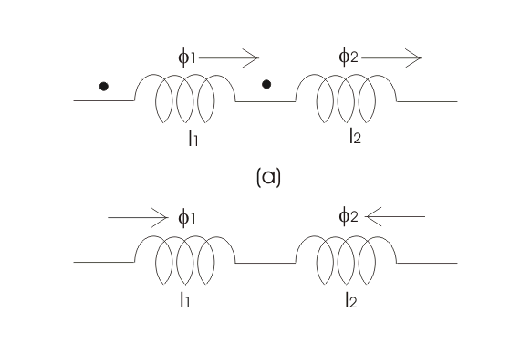
Let us consider two coils connected in series as shown in figure given below.
Such that the magnetic fields are additive, the resultant inductor of these two can be calculated as
Where, L1 is the self inductor of first coil,
L2 is the self inductor of second coil,
M is the mutual inductor of these two coils.
Now if the connections of any one of the coils is reversed then we have
On solving these two equations we have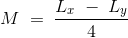
Thus the mutual inductor of the two coils connected in series is given by one-fourth of the difference between the measured value of self inductor when taking the direction of field in the same direction and value of self inductor when the direction of field is reversed.

However, one needs to have the two series coils on the same axis in order to get most accurate result. Let us consider the circuit of Heaviside mutual inductor bridge, given below,
Main application of this bridge in industries is to measure the mutual inductor in terms of self inductance. Circuit of this bridge consists of four non inductive resistors r1, r2, r3 and r4 connected on arms 1-2, 2-3, 3-4 and 4-1 respectively. In series of this bridge circuit an unknown mutual inductor is connected. A voltage is applied to across terminals 1 and 3. At balance point electric current flows through 2-4 is zero hence the voltage drop across 2-3 is equal to voltage drop across 4-3. So by equating the voltage drops of 2-4 and 4-3 we have,
Also we have,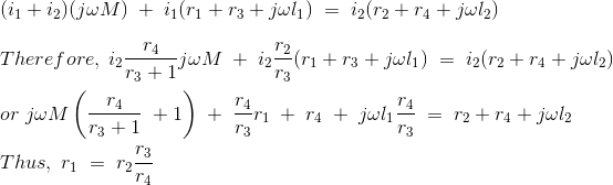
and mutual inductor is given by,
Let us consider some special case,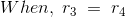
In this case the mutual inductor is reduced to
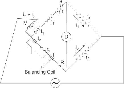
Now let us consider the circuit of Campbell’s Heaviside bridge given below:
This is the modified Heaviside bridge. This bridge is used to measure the unknown value of self inductor in terms of mutual inductance.The modification is due to addition of balancing coil l, and R in arm 1 – 4 and also electrical resistance r is included in arm 1-2. Short circuit switching is connected across r2 and l2 in order to have two sets of readings one while short circuiting r2 and l2 and other while open circuiting r2 and l2.
Now let us derive the expression for self inductor for this modified Heaviside bridge. Also let us assume that the value of M and r with switch open be M1 and r1, M2 and r2 with switch closed.
For open switch, we have at balance point,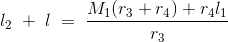
and with closed switch we can write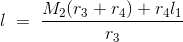
Thus we final expression for self inductor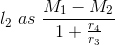
")
")


Great just love this ,it has really helped me
Very happy to hear that Bella. Thank you for your kind words.