

- Self Induction Definition: Self induction is a phenomenon where a changing electric current induces an emf across the coil itself.
- Self Inductance: Self inductance is the ratio of the induced emf across a coil to the rate of change of current through it, denoted by L and measured in Henry (H).
- Lenz’s Law: The induced emf opposes the change in current, which is why there is a negative sign in the equation, following Lenz’s Law.
- Faraday’s Law: By applying Faraday’s Law of Electromagnetic Induction, the induced emf in a coil can be calculated from the changing magnetic flux.
- Inductive Reactance: In AC circuits, self-inductance results in inductive reactance (XL = 2πfL), which depends on the frequency of the AC supply.
Self Induction
Self-induction occurs when a changing electric current changes the magnetic flux linked with its own circuit and induces an emf in that same circuit.
Self Inductance
Self-inductance, denoted by L, relates a circuit’s current to the magnetic flux linkage that the current produces. For a linear magnetic system, the flux linkage equals Li. The SI unit is the henry (H), equivalent to one weber per ampere.
When L is constant, the magnitude of induced emf is proportional to the rate of change of current: 
The signed relation is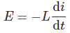
Why is there a minus sign?
Under Lenz’s Law, the induced emf has the polarity that opposes the change that produces it. The minus sign expresses this direction. When only the positive value of L is required, use the magnitudes of emf and the current’s rate of change.
Derivation of Inductance
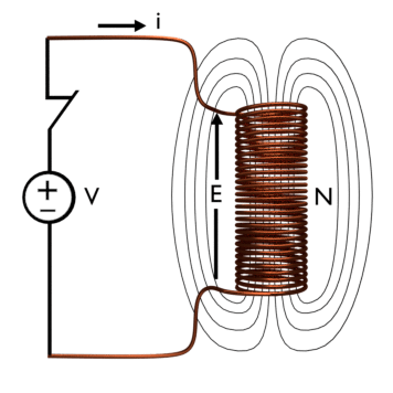
Consider a coil connected to a DC source. Immediately after the switch closes, at t = 0+, current rises from zero rather than changing instantaneously. The changing current produces a changing magnetic flux φ through each turn, so the flux has a non-zero time derivative: 
Applying Faraday’s Law of Electromagnetic Induction gives
Here, N is the number of turns and e is the induced emf across the coil.
With the polarity convention from Lenz’s law, the equation becomes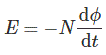
For a linear magnetic system, flux linkage is proportional to current. The proportionality constant is inductance.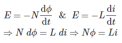
For the ideal long solenoid shown, substitute the uniform-field relations. 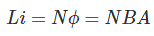 [B is the flux density i.e. B =φ/A, A is area of the coil], and the field is treated as uniform.
[Nφ or Li is called magnetic flux Linkage and it is denoted by Ѱ]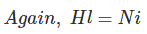 Here H is magnetic field strength, l is the effective solenoid length and the material relation uses its permeability.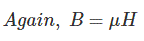


The cross-sectional area is πr², where r is the coil radius.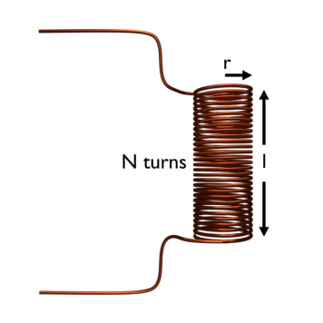
For an ideal long solenoid, L depends on permeability, cross-sectional area, effective length and the square of the turn count. A real coil can also be affected by leakage flux, fringing, air gaps, winding geometry and magnetic saturation. In a DC circuit, induced voltage exists whenever current changes. It becomes zero after an ideal steady current is established, then appears again when the current changes or the circuit opens.
With sinusoidal AC, current changes continuously and the ideal inductor’s voltage leads its current by 90 degrees. Its inductive reactance is XL = 2πfL, where f is frequency and L is inductance. Reactance is measured in ohms. This formula describes sinusoidal steady-state operation; other waveforms are analysed directly from the time-domain voltage-current relation.


