- Electromagnetic Relay Definition: An electromagnetic relay is a switch that uses an electromagnet to mechanically operate a switching operation, essential in various electrical protection systems.
- Operation Principles: The working of electromagnetic relays involves principles like magnitude and ratio measurement, essential for understanding their functionality in electrical systems.
- Types of Relays: Different types of electromagnetic relays include attracted armature, induction disc, and moving coil, each suited for specific applications.
- Induction Disc Operation: Induction disc relays generate motion and operate based on the interaction of magnetic fields and a rotating disc, a key component in energy measurement.
- Relay Applications: Electromagnetic relays are crucial in managing electrical circuits by providing over-current protection, voltage regulation, and system stability.
Electromagnetic Relay
Electromagnetic relays use magnetic force to move an armature, disc, cup or coil and operate contacts. Digital electrical protection relays now combine many protection and monitoring functions, but electromagnetic relays remain in service in legacy installations. Engineers who maintain those schemes need to understand their operating elements and limits.
Electromagnetic Relay Working
Electromagnetic measuring relays respond to one or more operating quantities. The protected list groups their measuring action into three broad types of electromagnetic relays.
- Magnitude measurement,
- Comparison,
- Ratio measurement.
The principle of electromagnetic relay working depends on how electrical input produces mechanical torque or force. The following legacy classification lists common types of electromagnetic relays by their moving element or construction.
- Attracted Armature type relay,
- Induction Disc type relay,
- Induction Cup type relay,
- Balanced Beam type relay,
- Moving coil type relay,
- Polarized Moving Iron type relay.
Attraction Armature Type Relay
An attracted armature type relay uses magnetic attraction to move an iron armature towards an energised core. Depending on its coil and restraint, the element can operate as an auxiliary or control relay, or respond to current, voltage or impedance.
Common constructions use a hinged armature or a plunger. The movement operates contacts after the magnetic force exceeds the mechanical restraint in these types of electromagnetic relays.
For a simplified unsaturated magnetic circuit, the attraction force increases with the square of the air-gap magnetic flux. When coil current produces that flux, the operating force can be represented by the following ideal relation.
Here, F is net force, K represents the relay’s magnetic geometry, I is the rms coil current and K’ represents the restraining force.
Pickup occurs when the operating term KI2 reaches the restraint K’.
Actual pickup also depends on magnetic saturation, friction, spring setting and the changing air gap.
Within this simplified model, relay operation is influenced by the following factors.
- Ampere – turns developed by the relay operating coil,
- The size of air gap between the relay core and the armature,
- Restraining force on the armature.
Construction of Attracted Type Relay
A coil and magnetic core attract a hinged armature or plunger when the input reaches pickup. The mechanism then changes the state of normally open and normally closed contacts. An attracted armature type relay may use AC or DC excitation, depending on its design. It may also be self-resetting or mechanically latched, so manual reset is not a universal feature of these types of electromagnetic relays.
The basic element is often described as instantaneous
, although its mechanical operating time and any added delay still depend on the relay design.
Induction Disc Type Relay
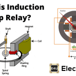
An induction disc type relay uses an aluminium or copper disc as its moving element. Alternating magnetic fluxes produce torque, while a spring and damping magnet control contact travel and timing.
Induction Disc type Relay Working
An induction disc type relay operates on the Ferraris induction principle. Two alternating fluxes that are displaced in phase induce disc currents and produce torque proportional to their magnitudes and the sine of their phase displacement.

This is related to the induction action used in an ammeter, an induction meter or a wattmeter, although their constructions and applications differ. Alternating eddy currents are induced in the conducting disc by the flux. With only one sinusoidal flux and an ideal resistive disc, the induced emf E2 lags the flux by 90o. The disc current I2 follows E2, so the angle between the flux and I2 is 90o and no average torque is produced.
A usable relay therefore creates two phase-displaced fluxes, which act like a rotating magnetic field and produce directional torque.
Pole Shading Method of Producing Torque in Induction Disc Relay
A copper shading ring surrounds part of the magnetic pole. Let φ1 represent the flux from the unshaded portion.
Current induced in the shading ring produces a delayed component φ2‘. The shaded-pole flux is the vector sum of φ1 and φ2‘. Call the resultant φ2. If the angle between φ1 and φ2 is θ, their interaction with the disc produces torque.
Relay manufacturers used round, spiral and vase-shaped discs. A spiral profile can compensate for the increasing control-spring restraint as the disc turns, while contact geometry sets the required travel and pressure. Some long-travel designs can approach 280o, but the actual angle is model-specific.
A short-travel circular or vane
element can reduce operating time where faster action is required.
A separate shading coil can also place the element under external control. If another device closes the coil circuit, the resulting phase displacement permits the disc to develop operating torque.
Resistance in that shading-coil circuit changes flux phase displacement and can alter the time-current characteristic.
When supplied through a suitable negative-sequence filter, an induction disc element can provide negative-sequence protection for alternators.
Induction Cup Type Relay
An induction cup type relay uses the same induction principle as a disc relay but replaces the disc with a light conducting cup. An Induction cup type relay can accommodate polarising and operating windings around a multi-pole magnetic structure. Four- and eight-pole arrangements are common in legacy designs.
The cup’s low inertia permits less travel and faster response than many induction disc designs. Flux from one pole pair produces eddy currents that interact with flux from another pair, creating torque. Exact speed and torque-per-VA values depend on the relay model.
An induction cup type relay is well suited to directional and phase-comparison elements. A correctly designed induction cup relay develops steady torque from the intended relationship between current and voltage, while limiting torque from either quantity alone.
Induction Cup Type Directional or Power Relay
In a four-pole induction cup element, one pole pair can produce a voltage-derived flux and the other a current-derived flux.
For the notation shown, T1 = Kφviφi sin(90o − θ). The voltage-coil circuit sets the phase shift of its flux. Relay design can therefore produce a characteristic such as T = KEI cos(φ − θ), where θ represents the chosen maximum-torque angle.
Legacy induction-cup units were available with maximum-torque angles such as 0o, 30o, 45o or 60o. A unit may be called a power relay
when it produces maximum torque at 0o. Directional protection uses a selected angle that gives dependable operating and restraining regions for the intended fault conditions.
Reactance or Mho Type Induction Cup Relay
By selecting the current and voltage coil connections and their phase shifts, an induction cup element can implement a reactance or mho distance characteristic. Its operating region is set by the relay’s torque equation, not by a direct measurement of pure reactance alone.
Balanced Beam Relay
A balanced beam relay is an attracted-armature mechanism that compares operating and restraining forces on opposite sides of a pivoted beam.
Legacy differential and distance schemes used this arrangement before induction cup type relays and later solid-state or digital relays became common.
Under normal conditions, operating and restraining torques keep the beam away from its trip position.
A spring, a restraining coil or both can provide the restraining torque.
When fault current raises the operating torque above the restraint and pickup setting, the beam moves and closes the relay’s normally open trip contact.
Two typical mechanical arrangements are shown below.

Balanced beam elements are now mainly legacy equipment, so their application, test limits and maintenance method must come from the specific manufacturer’s instructions.
Known limitations include a relatively poor reset-to-pickup ratio, sensitivity to phase displacement between energising quantities and unwanted operation during some transients.
Moving Coil Type Relay
A polarised DC moving coil relay develops torque from the interaction between coil current and a permanent magnetic field. Its low operating power made it suitable for sensitive measurement in legacy distance and differential schemes. The moving element is inherently a DC device, so an AC input requires a suitable rectifier and interface connected to the instrument transformer.
A rectifier allows an AC-derived input to operate the DC moving element, but its polarity, burden and waveform response must match the relay design.
In a moving coil relay, the coil may move axially or rotate. Flexible leads carry current to the light moving assembly, so shock, friction and lead stiffness can affect a sensitive element.
Axial and rotary constructions have different sensitivity and damping characteristics. Numerical sensitivity or operating-time claims must be taken from the manual for the exact relay model.