

- Induction Cup Relay Definition: An induction cup relay is a type of relay that uses an aluminum cup instead of a disc, providing faster operation and higher torque.
- Working Principle: It operates on the same principle as an induction motor, where a rotating magnetic field induces current in the aluminum cup, causing it to rotate.
- Construction: The relay is constructed with laminated steel sheets and projected poles, with field coils wound on these poles to create the magnetic field.
- Directional Use: Induction cup relays are ideal for directional or phase comparison units due to their sensitivity and steady torque.
- Types of Relays: Different types of induction cup relays are designed to produce maximum torque at specific angles, suitable for various protection applications.
Induction Cup Relay
Induction cup relays are legacy electromechanical measuring units related to induction-disc relays. Their magnetic structure resembles a small multiphase induction motor, but the aluminium cup turns through only the short angle needed to operate contacts. Four-pole and eight-pole structures were common, with the pole and winding arrangement chosen for the required protective relay function.
A thin cup has lower rotational inertia than a solid disc. With a suitable magnetic circuit, this gives a high torque-to-inertia ratio and fast operation. The actual operating time, input burden and torque depend on the relay model rather than the cup shape alone.
In a four-pole unit, flux from each pole pair induces an eddy current in the conductive cup. The interaction between each flux and current induced by the other flux produces net torque when the fluxes have a phase displacement. Some designs produce more torque per volt-ampere than an induction-disc mechanism, but a fixed three-times value is not universal. The usable range also depends on air gaps, spring torque and magnetic saturation.
Working Principle of Induction Cup Relay
The working principle of induction cup relay uses electromagnetic induction, like an induction motor. Two or more alternating pole fluxes with a phase difference form a shifting or rotating magnetic field. Their interaction with currents induced in the cup creates operating torque. The quantity and phase-shift circuits depend on the relay function. In some single-input elements, both pole pairs can be supplied from the same current transformer’s secondary. An inductor in one branch and a resistor in another can provide the required phase displacement. Directional and distance units instead use different measured quantities and design networks.
The field induces current in the aluminium drum or cup. As in the working principle of induction motor, interaction between the induced current and the rotating magnetic field produces torque. The cup does not accelerate to a steady speed near synchronous speed. A spindle, control spring, stops and contacts restrict its movement to a small angle. In the reset state, spring torque holds the moving contact open or in its normal position. When the measured quantities produce enough operating torque, the cup turns until the contact changes state. High current is one possible operating quantity, but directional-power and distance units respond to combinations of current, voltage and phase angle.
Construction of Induction Cup Relay
The magnetic structure is assembled from laminated steel with pole faces projecting towards the cup. Lamination reduces unwanted eddy-current loss in the iron.
Field coils are fitted to the poles. Opposite poles may form a pole pair, while the external connections create the amplitude and phase relationship required by the relay characteristic.
The thin aluminium cup is mounted on a spindle and rotates in the annular air gap between the outer pole structure and a stationary laminated inner core. Jewel bearings or similar bearings support the spindle. A spring supplies reset torque, while an arm on the spindle carries the moving contact. The inner core lowers magnetic reluctance and guides the magnetic field through the cup.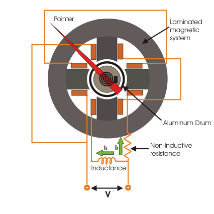
Induction Cup Directional or Power Relay
Induction-cup mechanisms were used for directional, power and phase-comparison units because their low inertia supports fast operation. A well-designed unit can limit torque from current or voltage alone, but the degree of suppression and sensitivity are model-specific.
In a directional or power unit, one magnetic circuit receives a polarising quantity from a voltage source, while another receives an operating quantity from a current source. In practice these signals normally come through voltage and current transformers. One flux follows the voltage circuit and the other follows the current circuit, with intentional phase shifts set by the relay design.
The vector diagram below shows a simplified power-unit relationship.
Let θ be the phase angle between system voltage V and current I.
Let current-circuit flux φ1 be in phase with I for this simplified derivation.
Let voltage-circuit flux φ2 lag V by 90 degrees.
The angle between φ1 and φ2 is then (90o – θ).
If the interaction of these two fluxes produces torque Td, the simplified relation is:
K is the proportionality constant for this model.
The equation assumes the voltage flux lags its voltage by 90o. A practical relay can shift the maximum-torque angle and may include spring, restraint and calibration terms. Its directional torque is commonly written in the form T = KVIcos (θ – φ). Example designs may place φ at 30o, 45o or 60o.
A unit designed for maximum torque near θ = 0 is a power or reverse-power element.
Units whose maximum-torque angle is θ = 45o or 60o can provide directional fault protection when their polarising quantities, pickup and contact logic are applied as specified.
Reactance and MHO type Induction Cup Relay
An induction cup relay can implement reactance, mho, admittance or angle-impedance characteristics by combining current-operated, voltage-operated and polarising torques. A link to admittance alone does not define the characteristic. The complete operating and restraining torque equation sets the reach, directional boundary and maximum-torque angle. These mechanisms are now mainly encountered in legacy distance and out-of-step protection, so maintenance and testing should use the exact manufacturer’s manual and settings.


