

- Electrical Circuit Definition: An electrical circuit is a closed loop made up of components like batteries and resistors that allow electric current to flow.
- Component Function: The main roles of electrical circuit components include delivering power, controlling and regulating flow, and protecting against electrical faults.
- Current Flow: In electrical circuits, electrons flow from the negative to the positive terminal, establishing a basis for how devices operate.
- Circuit Types: Different types of circuits such as open, closed, short, series, and parallel are crucial for understanding how electrical systems are structured and function.
- Practical Application: Most real-world electrical systems use series-parallel circuits, demonstrating the need for a versatile approach in electrical design.
What is an Electrical Circuit?
An electrical network is an interconnection of active and passive components. A circuit is a network that contains one or more closed paths. A steady Electric current requires a complete conducting path, but engineers also analyse open networks in which current is zero in a broken branch.
The main parts of an ideal electric circuit are:
- Electrical sources, such as batteries or generators, that establish voltage or current and transfer energy
- Control devices, such as switches, relays and variable components, that change a circuit state or operating value
- Protection devices, including electric fuses, MCBs and coordinated switchgear systems, that interrupt defined fault conditions
- A conducting path that carries electric current between nodes, usually through wires, printed traces or other conductors
- A load or other element that converts, stores or transfers electrical energy.
voltage is measured between two points, while current is defined through a branch. Circuit analysis uses component relations with Kirchhoff’s current and voltage laws to determine these quantities for each electric element.
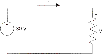
The figure shows a simple ideal DC circuit containing:
- A 30 V battery
- A 5 kΩ carbon resistor
With an ideal 30 V source and 5 kΩ load, Ohm’s law gives a current of 6 mA. The entire source potential drop appears across the only resistor. Real source and wire resistance can change the result.
Basic Properties of Electric Circuits
The basic properties of electric circuits include:
- A conducting current path is closed. A circuit diagram can also represent an open switch or broken branch.
- An active circuit normally includes a source that transfers energy. The source drives existing charge carriers; it is not a consumable source of electrons.
- Elements can include independent or controlled sources, resistors, capacitors, inductors and semiconductor devices.
- In a metallic DC conductor, electron drift is opposite to conventional current. Other media can have different charge carriers.
- Conventional current leaves the positive terminal of a discharging source through the external circuit and returns to its negative terminal.
- Element voltage follows its constitutive relation and chosen polarity. A source can provide a voltage rise, while a passive load usually has a drop in the current direction.
Types of Electric Circuits
The main types of electric circuits are:
- Open circuit
- Closed circuit
- Short circuit
- Series Circuit
- Parallel Circuit
- Series Parallel Circuit
Open Circuit
An open circuit has a broken conducting path. Current is zero through the open branch in the ideal model, although a voltage can remain across the opening.

Closed Circuit
A closed circuit has a complete path. Current flows only when a source establishes a voltage and the total impedance is finite.

Short Circuit
A short circuited condition is an unintended or intentional connection with much lower impedance than the normal load path. Examples include phase-to-phase, phase-to-neutral, phase-to-earth or opposite-polarity DC faults. Real faults do not have exactly zero impedance, but they can still produce destructive current and arc energy.

Electric circuits can be further categorized according to their structural features into either:
- Series Circuits
- Parallel Circuits
- Series Parallel Circuits
Series Circuit
elements of a circuit are in a series circuit when the same branch current must pass through each element and their shared nodes have no other current paths.
The same current flows through ideal series-connected elements. Kirchhoff’s voltage law relates the signed element voltages around the complete loop.

Parallel Circuit
Components connected between the same two nodes have the same voltage drop. This arrangement is a parallel circuit.
In a parallel circuit, each branch has the same voltage drop. Branch currents can differ, and Kirchhoff’s current law gives their signed sum at a node.
Household branch loads are commonly connected as a parallel circuit so each receives the supply voltage. If one electric lamp opens, other healthy branches can continue operating, subject to their protective devices.
The voltage is the same only for elements connected across the same two nodes.
When the resistors are connected in parallel:

For finite positive resistors, the total resistance is the reciprocal of the sum of their reciprocal resistances.
When the inductors are connected in parallel:

For ideal, linear and uncoupled inductors in parallel, reciprocal equivalent inductance equals the sum of reciprocal branch inductances. Mutual coupling changes this relation.
When the capacitors are connected in parallel:

capacitors connected in parallel share the same voltage; they do not act as a series combination. For ideal capacitors, total capacitance is the sum of the individual capacitances.

Series Parallel Circuit
A series-parallel circuit contains both series-connected and parallel-connected groups. It can often be reduced in stages when the topology contains clear series and parallel combinations.
Many practical circuits combine series and parallel paths, but not every network can be reduced by simple series-parallel rules. The conductor paths in some DC motor armatures provide one application, with the exact connection set by the winding design.


