

- Zener Diode Definition: A Zener diode is a special type of diode that allows current to flow in reverse without damage when the voltage exceeds a certain threshold known as the Zener breakdown voltage.
- Characteristics of Zener Diode: This diode’s key feature is its ability to handle reverse voltage up to a certain limit, known as the Zener breakdown voltage, beyond which it conducts large currents without being destroyed.
- Voltage Regulation: Zener diodes are crucial in maintaining steady voltage levels, making them essential for voltage stabilizers and protective circuits.
- Symbol and Identification: The symbol for a Zener diode is distinct, featuring a diode pointing in the reverse direction, which helps in easy identification in circuit diagrams.
- Operational Advantage: Unlike ordinary diodes, Zener diodes regain their original depletion region after the removal of the reverse voltage, a characteristic that prevents damage and prolongs their operational life.
Ordinary diodes primarily work when forward biased, allowing substantial current with minimal voltage drop. In reverse bias, they conduct only a minimal current until the reverse breakdown voltage is exceeded. At this point, a large current can destroy the diode.
The Zener diode addresses this limitation by operating safely in reverse-biased conditions, enduring excess voltage without damage. Let’s explore this unique and robust type of diode.
Zener diodes are more heavily doped than ordinary diodes, resulting in an exceptionally thin depletion region. Applying voltage above the Zener breakdown voltage (ranging from 1.2 to 200 volts) causes this region to vanish, prompting a large current flow through the junction. There is a crucial difference between an ordinary diode and a Zener diode. The depletion region regains its original position after removal of the reverse voltage in Zener diode whereas in regular diodes, they don’t, and hence they get destroyed.
Here is the Zener diode symbol
Let us now look at the Zener diode characteristic: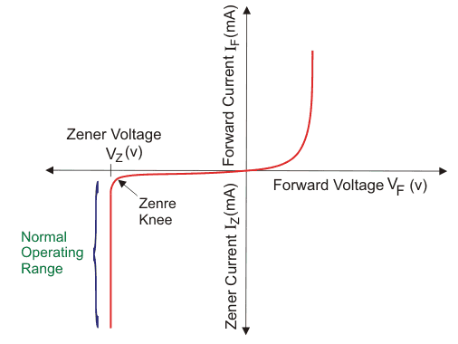
A graph of current through vs the voltage across the device is called the characteristic of Zener diode. The first quadrant is the forward biased region. Here the Zener diode acts like an ordinary diode. When a forward voltage is applied, current flows through it. But due to higher doping concentration, higher current flows through the Zener diode. In the third quadrant, the magic happens. The graph shows the current vs voltage curve when we apply a reverse bias to the diode. The Zener breakdown voltage is the reverse bias voltage after which a significant amount of current starts flowing through the Zener diode. Here in the diagram, VZ refers to the Zener breakdown voltage. Until the voltage reaches Zener breakdown level, tiny amount of current flows through the diode. Once the reverse bias voltage becomes more than the Zener breakdown voltage, a significant amount of current starts flowing through the diode due to Zener breakdown. The voltage remains at the Zener breakdown voltage value, but the current through the diode increases when the input voltage gets increased. Due to the unique property of Zener diode, the depletion region regains its original position when the reverse voltage gets removed. The Zener diode doesn’t get damaged despite this massive amount of current flowing through it. This unique functionality makes it very useful for many applications.
Since the voltage stabilizes at the Zener breakdown voltage, Zener diodes for voltage regulation. They are employed in voltage stabilizers, protection circuits, clipping circuit and clamping circuit, offering an affordable solution for managing voltage.
")


