

- Zener Diode Definition: A Zener diode is defined as a diode that operates in reverse bias to regulate voltage.
- Reverse Biased Operation: Zener diodes work in reverse bias due to their narrow depletion region, which prevents damage.
- Breakdown Voltage: Zener diodes have a specific breakdown voltage where they maintain a constant voltage drop despite increased current.
- Voltage Regulation with Zener Diodes: Zener diodes are used as voltage regulators by maintaining a steady voltage across a load, even if input voltage fluctuates.
- Circuit Diagram Explanation: In a circuit, a Zener diode is connected in reverse bias parallel to the load, ensuring the voltage across the load does not exceed the breakdown voltage.
A Zener diode is a specially designed diodes device made to run in reverse breakdown. These diodes are more heavily doped than ordinary rectifiers, so low-voltage types have a thin depletion region. A rectifier diode is not rated for continuous reverse breakdown voltage. A Zener diode is. The junction recovers when the reverse voltage is removed, if it was not overheated. That reverse-breakdown rating is why Zener diodes are used as voltage regulators.
Before understanding how a Zener diode acts as a voltage regulator, look at the reverse characteristic.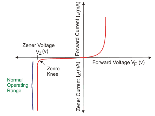
When a reverse voltage is applied to a Zener diode, only a small current flows. If the voltage exceeds the Zener breakdown voltage, current rises while the voltage across the part stays near that knee. As the reverse voltage source tries to rise, the voltage across the diode stays near the breakdown value and the current continues to rise. Catalogue breakdown voltages typically run from about 2.4 V to 200 V. Parts below about 5 V are true Zener (tunneling); higher voltages are mostly avalanche, still sold as Zener diodes.
We can choose a Zener diode with a specific breakdown voltage to use it as a voltage regulator in a circuit. For instance, if the voltage across a load must stay near 12 volts, use a 12-volt Zener and a series resistor from the unregulated supply. If the input stays high enough, and Zener current stays between the knee and the rated maximum, the load voltage stays near 12 V.
Let us try to understand that with a circuit diagram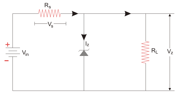
Here the Zener diode is connected across the load RL, after a series resistor. We want the voltage across the load to stay near Vz. Depending on our requirement, we choose the suitable Zener diode with a Zener breakdown voltage near to the voltage we require across the load. We connect the Zener diode in reverse bias condition. When the voltage across the diode exceeds the Zener breakdown voltage, a larger current starts flowing through the diode. As the load is in parallel to the diode, the voltage drop across the load is also equal to the Zener breakdown voltage. The series resistor drops the extra source voltage. The Zener does not protect the load from overcurrent; it holds the voltage. Thus the Zener diode serves as a Zener diode as a voltage regulator. Excess source current is limited by the series resistor, not by the Zener acting as a fuse.


