- Vector Impedance Meter Definition: A vector impedance meter is defined as a device that measures both the amplitude and phase angle of impedance in AC circuits.
- Measuring Amplitude and Phase Angle: It determines the impedance in polar form by evaluating the voltage drops across resistors and unknown impedances.
- Equal Deflection Method: This method ensures equal voltage drops across a variable resistor and the unknown impedance to find the impedance value.
- Commercial Vector Impedance Meter: Offers direct measurement of impedance with high accuracy and a wide range of frequency applications.
- Applications and Benefits: Used for measuring complex impedances and simplifies the process by eliminating the need for multiple adjustments.
Impedance has both a magnitude and a phase, and it opposes the flow of current in AC circuits when an applied voltage drives them.
The Vector Impedance Meter measures both the amplitude and the phase angle of an impedance (Z).
In most other measuring techniques, the individual values of resistance and reactance are obtained in rectangular form, namely 
This meter instead obtains the impedance in polar form: its magnitude |Z| and phase angle (θ) can be acquired directly. The circuit is shown below.
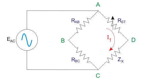
Two resistors of equal resistance are incorporated here. The voltage drop across RAB is EAB and that across RBC is EBC. Both values are equal, each being half the input voltage (EAC).
A variable standard resistance (RST) is connected in series with the impedance (ZX) whose value is to be obtained.
The equal deflection method determines the magnitude of the unknown impedance.
It does so by achieving equal voltage drops across the variable resistor and the impedance (EAD = ECD) and then reading the calibrated standard resistor (here it is RST) required to reach this condition.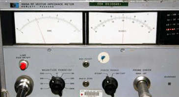
The phase angle of the impedance (θ) follows from the voltage reading taken across BD, namely EBD.
The meter deflection varies with the Q factor (quality factor) of the connected unknown impedance.
The Vacuum Tube Voltmeter (VTVM) reads AC voltage from 0 V up to its maximum value. When the reading is zero, Q is zero and the phase angle is 0 degrees.
When the reading reaches the maximum value, Q is infinite and the phase angle is 90o.
The angle between EAB and EAD equals θ/2, half of the phase angle of the unknown impedance, because EAD = EDC.
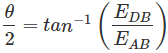
The voltage across A and B (EAB) equals half of the voltage across A and C (EAC, the input voltage), so the reading of the voltmeter, EDB, can be expressed in terms of θ/2. The phase angle θ can therefore be determined. The vector diagram is shown below.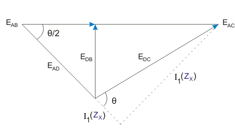
This method suits a first approximation of the magnitude and phase angle; for more accuracy the commercial vector impedance meter is preferred.
Commercial Vector Impedance Meter
A commercial vector impedance meter measures impedance directly in polar form, using one control to find both the phase angle and the magnitude.
It handles any combination of resistance (R), Capacitance (C) and Inductance (L). It also measures complex impedances rather than pure elements alone (C, L or R).
The main drawback of conventional bridge circuits, too many successive adjustments, is eliminated here. Impedances from 0.5 to 100,000 Ω can be measured over the frequency range 30 Hz to 40 kHz when an external oscillator provides the supply.
Internally, the meter generates frequencies of 1 kHz, 400 Hz or 60 Hz, and externally it operates up to 20 kHz. Accuracy is ±1% for magnitude and ±2% for phase angle.
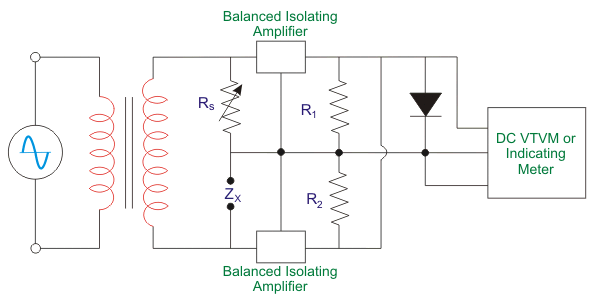
The circuit for measuring the magnitude of the impedance is shown below.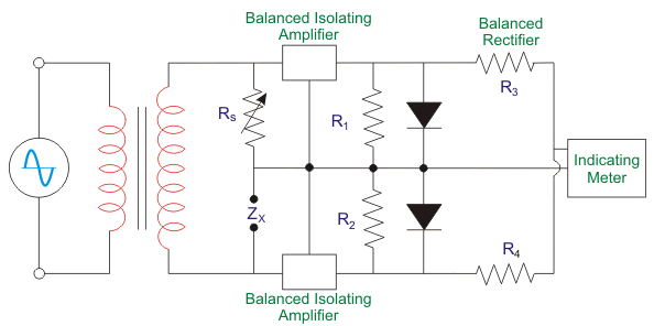
For the magnitude measurement, RX is the variable resistor, altered through the calibrating impedance dial.
The dial is adjusted until the voltage drops across the variable resistor and the unknown impedance (ZX) are equal. Each voltage drop is amplified by two modules of balanced amplifiers.
The amplified signals then feed the connected dual rectifier section, where the arithmetic sum of the rectifier outputs becomes zero, shown as the null reading on the indicating meter. The unknown impedance can then be read directly from the dial of the variable resistor.
Next consider how the meter obtains the phase angle. First the switch moves to the calibration position and the injected voltage is calibrated.
This calibration sets the injected voltage so the VTVM or indicating meter shows full-scale deflection.
After that, the function switch moves to the phase position. In this condition the function switch connects the outputs of the balanced amplifier in parallel before rectification.
The total AC voltage arriving from the amplifiers is then a function of the vector difference between the AC voltages at the amplifiers.
The voltage rectified from this vector difference appears on the indicating meter or DC VTVM. It measures the phase angle between the voltage drop across the unknown impedance and that across the variable resistor.
Those two voltage drops are equal in magnitude but differ in phase, so the instrument reads out the phase angle directly.
The quality factor and dissipation factor can also be calculated from this phase angle if needed.
The circuit diagram for the measurement of phase angle (θ) is shown below.