- Schering Bridge Definition: The Schering Bridge is defined as an electrical circuit used for precise measurements of a capacitor’s capacitance, dissipation factor, and the relative permittivity of materials.
- Measuring Capacitance: The Schering Bridge measures capacitance by adjusting the impedance of its components to balance the bridge, where no voltage is detected across specific points.
- Components and Configuration: Essential components of a Schering Bridge include standard and variable capacitors, as well as non-inductive resistors, all crucial for accurate measurements.
- High Voltage Application: High voltage Schering Bridges are specifically used for measuring small capacitances in materials that require high voltages for better precision.
- Calculating Relative Permittivity: Relative permittivity is calculated from the capacitance measured across a specimen, considering factors like electrode area and spacing, enhancing understanding of material properties.
Schering Bridge Theory
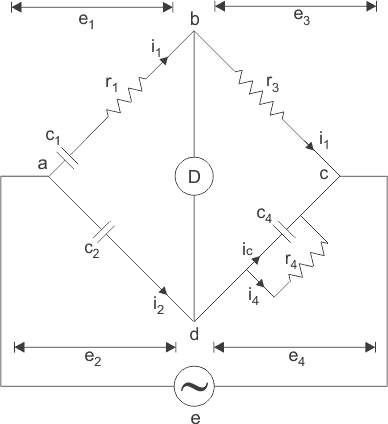
A Schering Bridge is an AC four-arm network that measures a capacitor’s capacitance and its dissipation factor. The same reading, with known electrode geometry, gives relative permittivity of a dielectric. The Schering Bridge circuit is below.
c1 is the unknown capacitance. r1 is its series equivalent loss resistance.
c2 is a low-loss standard capacitor.
c4 is a variable capacitor.
r3 is a non-inductive resistor.
r4 is a variable non-inductive resistor in parallel with capacitor c4. The source feeds a and c. The detector sits between b and d. At null the AC-bridge product rule holds:

Substituting the values of z1, z2, z3 and z4 in the above equation, we get
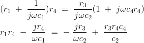
Split real and imaginary parts to get:


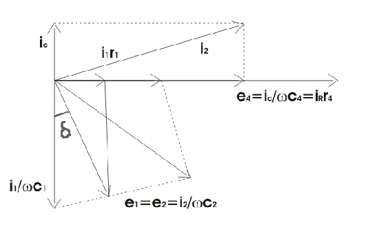
On the phasor diagram of that Schering circuit, mark the voltage drops across ab, bc, cd and ad as e1, e3,e4 and e2. tanδ from that diagram is the dissipation factor D.
D follows from the stored formula. The low-voltage Schering set is for laboratory capacitors and some dielectric samples, including insulating oil. High-voltage Schering is the insulation-test form.
A high-voltage Schering Bridge is used when the specimen is insulation that must be stressed at power-frequency kilovolts. The extra voltage raises the current through a small C so the null is readable. The usual source is still 50 or 60 Hz, not a radio-frequency bridge. Features of that HV layout:
- Arms ab and ad are capacitors, so their impedances are large next to bc and cd. Arm bc is resistor r3. Arm cd is capacitor c4 in parallel with resistor r4. The drop on bc and cd stays small. Point c is earthed, so the voltage on bc and dc is only a few volts above earth.
- High voltage comes from a transformer at 50 Hz. The classic detector is a vibration galvanometer tuned to that frequency.
- The large impedances of ab and ad keep the drawn current and the power loss low. The detector must still resolve that small current at null.
- The standard capacitor c2 uses compressed gas as dielectric, so its dissipation factor is treated as near zero. Earthed screens between the high and low arms cut stray capacitance error.
Relative permittivity from a Schering reading:
Measure the capacitance of a small cell that uses the specimen as dielectric. Parallel-plate geometry then gives relative permittivity from
Where r in that GIF is relative permittivity, not permeability.
c is the capacitance with the specimen as dielectric.
d is the spacing between the electrodes.
A is the net area of the electrodes.
ε is permittivity of free space.
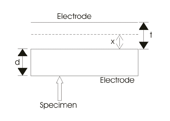
A second method changes electrode spacing. The sketch below is that cell.
A is the electrode area.
d is the specimen thickness.
t is the gap between electrode and specimen, filled with compressed gas or air.
cs is the specimen capacitance.
co is the capacitance of that air or gas gap.
c is the series combination of cs and co.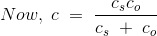
Those two capacitors are in series, so
εo is permittivity of free space. εr is relative permittivity. Remove the specimen and reset the gap until C is the same. Capacitance then reduces to
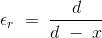
Equate (1) and (2) to get εr: