

- Parallel RLC Circuit Definition: A parallel RLC circuit consists of a resistor, inductor, and capacitor connected parallel to a voltage source, with each component maintaining the same voltage across it.
- Voltage and Current Relationship: The voltage across each component in a parallel RLC circuit is constant, whereas the current varies according to each component’s impedance.
- Kirchhoff’s Law in Action: In parallel RLC circuits, Kirchhoff’s current law confirms that the sum of currents entering a node is equal to the sum leaving, crucial for understanding circuit flow.
- Understanding Admittance: In parallel RLC circuits, total admittance is calculated by adding the admittance values of individual components, which helps simplify analysis.
- Resonance Characteristics: At resonance, a parallel RLC circuit’s impedance is at its maximum, and the circuit acts purely resistive, achieving a unity power factor.
Consider a parallel RLC circuit where the resistor, inductor and capacitor are connected alongside each other, all powered by the same voltage supply, VS. This configuration contrasts with the series RLC circuit, highlighting a unique setup.

In a series RLC circuit, the same current flows through the resistor, inductor, and capacitor. In contrast, a parallel RLC circuit maintains the same voltage across each component but divides the current based on each component’s impedance, illustrating its dual nature compared to the series circuit.
The total current, IS, from the supply equals the vector sum of the resistive, inductive, and capacitive currents. These currents cannot be summed directly since they are not in phase with each other.
Apply Kirchhoff’s current law, which states that the sum of currents entering a junction or node, is equal to the sum of current leaving that node we get,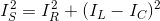
Phasor Diagram of Parallel RLC Circuit
Let V is the supply voltage.
IS is the total source current.
IR is the current flowing through the resistor.
IC is the current flowing through the capacitor.
IL is the current flowing through the inductor.
θ is the phase angle difference between supply voltage and current.
For drawing the phasor diagram of parallel RLC circuit, voltage is taken as reference because voltage across each element remains the same and all the other currents i.e IR, IC, IL are drawn relative to this voltage vector. We know that in case of resistor, voltage and current are in same phase; so draw current vector IR in same phase and direction to voltage. In case of capacitor, current leads the voltage by 90o so, draw IC vector leading voltage vector, V by 90o. For inductor, current vector IL lags voltage by 90o so draw IL lagging voltage vector, V by 90o. Now draw the resultant of IR, IC, IL i.e current IS at a phase angle difference of θ with respect to voltage vector, V.
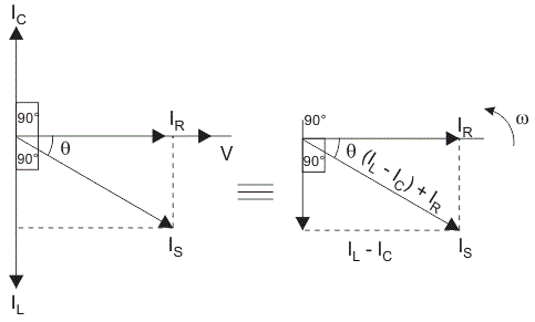
Simplifying the phasor diagram, we get a simplified phasor diagram on right hand side. On this phasor diagram, we can easily apply Pythagoras’s theorem and we get,
Impedance of Parallel RLC Circuit
From the phasor diagram of parallel RLC circuit we get,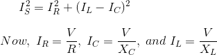
Substituting the value of IR, IC, IL in above equation we get,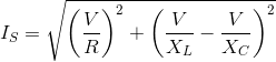
On simplifying,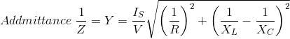
As shown above in the equation of impedance, Z of a parallel RLC circuit each element has reciprocal of impedance (1/Z) i.e admittance, Y. For solving parallel RLC circuit it is convenient if we find admittance of each branch and the total admittance of the circuit can be found by simply adding each branch’s admittance.
Admittance Triangle of Parallel RLC Circuit

Unlike series RLC circuits that focus on impedance, parallel RLC circuits emphasize admittance. Admittance inversely relates to impedance, comprising conductance (G), the reciprocal of resistance (R), and susceptance (B), the reciprocal of reactance (X). Thus, the admittance triangle in a parallel RLC circuit is the inverse of the series circuit’s impedance triangle.
Resonance in Parallel RLC Circuit
Like series RLC circuit, parallel RLC circuit also resonates at particular frequency called resonance frequency i.e. there occurs a frequency at which inductive reactance becomes equal to capacitive reactance but unlike series RLC circuit, in parallel RLC circuit the impedance becomes maximum and the circuit behaves like purely resistive circuit leading to unity electrical power factor of the circuit.
")
")

