

- Ring Counter Definition: A ring counter is a digital counting device that consists of flip-flops arranged in a shift register format with a unique connection that creates a circular counting sequence.
- Types of Ring Counters: There are two primary types of ring counters: straight, which uses a direct loop-back, and twisted, which incorporates an inverter for feedback.
- Operational Mechanics: Ring counters work by shifting a bit through flip-flops with each clock pulse, effectively counting and storing bits in a sequence.
- Advantages and Applications: Ring counters are straightforward to implement, have consistent timing, and are useful in applications requiring simple decoding and error detection.
- Design Variability: Depending on the design, ring counters can be used to create decorative patterns in LEDs, manage data in buffers, or control digital circuits in synchronous systems.
A ring counter consists of flip-flops arranged in a sequence where the output of the last flip-flop loops back to the first, forming a circular structure. A counter is a digital device that counts the number of pulses or events that occur in a given time interval. A flip-flop is a bi-stable device that can store one bit of information (0 or 1) and change its state in response to a clock signal. A shift register is a group of flip-flops that can store multiple bits of information and shift them along one position for each clock pulse.
What is a Ring Counter?
A ring counter is a specific type of shift register, where the output from the last flip-flop feeds directly back into the first, completing a circular data flow. The ring counter can be classified into two types: straight ring counter and twisted ring counter.
Straight Ring Counter
A straight ring counter, also known as a one-hot counter, connects the output of the last shift register to the first shift register input and circulates a single one (or zero) bit around the ring. The number of states in a straight ring counter is equal to the number of flip-flops used. For example, a 4-bit straight ring counter has four states: 1000, 0100, 0010, and 0001. The bit pattern repeats every four clock cycles.
The following figure shows a 4-bit straight ring counter made using D flip-flops. A D flip-flop is a type of flip-flop that transfers the input D to the output Q on the negative edge of the clock signal.

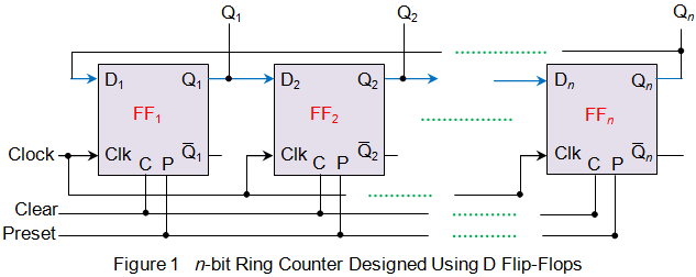
Here, the preset (P) pin initializes the counter by loading a chosen bit pattern, while the clear (C) pin clears every flip-flop in the chain. Both P and C are active-low signals: they act when pulled to 0. P at 0 forces Q to 1; C at 0 forces Q to 0, regardless of D and CLK.
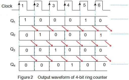
Usually, straight ring counters are loaded with a pattern where all bits are zeros except one bit, which is one. For example, a 4-bit straight ring counter can be loaded with 0001. As the output of the last flip-flop is connected back to the input of the first flip-flop, this bit pattern rotates within the counter by shifting its position once for each clock pulse.
The following table shows an example of such data movement for a 4-bit straight ring counter, pre-loaded with 1000. The corresponding waveforms are shown below.

| State | Q0 | Q1 | Q2 | Q3 |
|---|---|---|---|---|
| 0 | 1 | 0 | 0 | 0 |
| 1 | 0 | 1 | 0 | 0 |
| 2 | 0 | 0 | 1 | 0 |
| 3 | 0 | 0 | 0 | 1 |
| 0 | 1 | 0 | 0 | 0 |
Twisted Ring Counter
A twisted ring counter, also called switch-tail ring counter, walking ring counter, Johnson counter, or Möbius counter, connects the complement of the output of the last shift register to the input of the first register and circulates a stream of ones followed by zeros around the ring. The number of states in a twisted ring counter is twice the number of flip-flops used. For example, a 4-bit twisted ring counter has eight states: 0000, 1000, 1100, 1110, 1111, 0111, 0011, and 0001. The bit pattern repeats every eight clock cycles.
The following figure shows a 4-bit twisted ring counter made using D flip-flops. Here, an inverter (NOT gate) is used to complement the output Q3 before feeding it to D0.
Twisted ring counters start automatically from a zero-state without needing manual setup, unlike their straight counterparts. Once activated by a clock signal, the twisted ring counter shifts a one through the sequence until all positions are ones, then reverses to zeros, cycling through states automatically.
The following table shows an example of such data movement for a 4-bit twisted ring counter starting from 0000. The corresponding waveforms are shown below.

| State | Q0 | Q1 | Q2 | Q3 |
|---|---|---|---|---|
| 0 | 0 | 0 | 0 | 0 |
| 1 | 1 | 0 | 0 | 0 |
| 2 | 1 | 1 | 0 | 0 |
| 3 | 1 | 1 | 1 | 0 |
| 4 | 1 | 1 | 1 | 1 |
| 5 | 0 | 1 | 1 | 1 |
| 6 | 0 | 0 | 1 | 1 |
| 7 | 0 | 0 | 0 | 1 |
Properties and Applications of Ring Counters
Ring counters have some advantages and disadvantages compared to other types of counters. They also have some applications in hardware design and digital systems.
Advantages
- Ring counters are simple and easy to implement using shift registers and flip-flops.
- Ring counters have nearly constant propagation delay regardless of the number of bits in the code, whereas binary counters have higher propagation delay as the number of bits increases.
- Ring counters generate codes that are easy to decode without additional logic circuitry.
- Straight ring counters produce one-hot codes separated by a minimum Hamming distance of two, so any single-bit flip lands on an invalid pattern and is immediately detectable.
- Twisted ring counters have Gray codes that differ by only one bit between adjacent states, which can be useful if the bit pattern is going to be asynchronously sampled.
- Twisted ring counters can self-initialize from the all-zeros state without external presetting.
Disadvantages
- Ring counters use code space less densely than binary encoding. A binary counter reaches 2^N states with N bits, while a straight ring counter manages only N states and a twisted ring counter 2N states.
- Ring counters require more flip-flops than binary counters for the same number of states.
- Ring counters have limited applications compared to binary counters.
Applications
- Ring counters are often used in hardware design (e.g., ASIC and FPGA design) to create finite-state machines that control sequential logic circuits.
- Ring counters are used to generate timing signals for synchronous systems such as clocks, timers, frequency dividers, etc.
- Ring counters are used to implement circular buffers or queues in memory devices such as RAMs or FIFOs.
- Ring counters are used to generate pseudo-random numbers or sequences for encryption or testing purposes.
- Ring counters are used to create rotating displays or LED chasers for decorative or signaling purposes.
Conclusion
Close the loop from the last flip-flop back to the first and a shift register becomes a ring counter: one-hot and error-visible in straight form, self-starting with twice the states in twisted form. Decoding stays trivial and timing stays even; the price is flip-flops, more of them than a binary counter would need for the same state count. Where simple sequencing, clean decoding or error visibility matters more than density, a ring counter earns its place.


