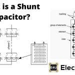
- Power Factor Correction Definition: Power factor correction (PFC) is defined as a technique to improve the power factor of AC circuits by reducing reactive power.
- Importance of PFC: It enhances the efficiency of electrical systems by lowering the current drawn from the source.
- PFC Formula: The capacitance needed for PFC is calculated by dividing the current by the product of angular frequency and voltage. This helps in determining the size of the capacitor required for improving the power factor.
- Capacitor Banks: Capacitor banks, which can be connected in delta or star configurations, are used to improve the power factor in three-phase systems.
- Active Power Factor Correction: This advanced method uses high-frequency switching elements to efficiently control the power factor in circuits with high power demands.
What is Power Factor Correction?
Power factor correction (PFC) raises the power factor of an AC circuit by cancelling some of the reactive power. For a given kW, that cuts the current drawn from the supply and the ohmic loss in feeders.
Shunt capacitors and over-excited synchronous motors supply leading vars that cancel lagging vars from inductive loads. For a fixed kW load, real power stays about the same. Apparent power falls, so kVA demand and line current fall.
That shrinks the phase shift between voltage and current (displacement power factor). Many utilities bill or penalise below about 0.9 to 0.95 lagging. A target in that band is common. The exact tariff number is local.
Why stop near 0.95 instead of 1.00?
NO extra displacement-kvar penalty remains at unity. Extra capacitor kVAr still costs money, can raise voltage on a light feeder and can sit on a harmonic resonance. Most plants therefore buy enough kVAr to meet the tariff, not a perfect 1.00.
That is why utilities and sites often design for 0.9 to 0.95 as an economic system rather than forcing every feeder to 1.00.
A heavily inductive plant can sit below 0.8 lagging. Line current is then higher than the kW alone would suggest.
PFC equipment supplies those vars locally so the source current falls and feeder loss falls. It does not create free energy. It avoids carrying vars over the supply cables.
Why Power Factor Correction is Needed?
On DC, a resistive load dissipates P = VI, and current follows Ohm’s law.
On AC, v and i are waves. Instantaneous power is v·i at that instant. Average real power is V I cosφ for sinusoids, not the V×I product used for apparent power.
Inductive loads such as windings, chokes, solenoids and transformers draw current that lags voltage. Real power is then less than the V×I product (apparent power).
A linear AC load has resistance and reactance, so current displaces from voltage. Non-linear loads add harmonic current. True power factor then includes both displacement and distortion. Shunt capacitors correct displacement vars. They do not remove harmonics and can amplify them if the bank resonates with the supply.
A pure resistor has voltage and current in phase. An inductor makes current lag and looks like inductive reactance.
That lagging current is what shunt PFC is sized to cancel, so the feeder carries fewer vars.
Power Factor Correction Formula
Take an inductive load running at cosф1. A shunt PFC device is connected in parallel with that load.
The circuit is shown below.

The capacitor draws a leading current that cancels part of the lagging load current. Before the capacitor, the load current is IL.
The capacitor current IC leads voltage by 90˚. The new line current is Ir. The angle between V and IR is smaller than the angle between V and IL, so cosф2 is higher (closer to 1 for a lagging load).

The phasor shows the remaining lagging component. Moving from ф1 to ф2, that remaining quadrature current is IRsinф2.
![\[ I_R sin \phi_2 = I_L sin \phi_1 - I_C \]](https://www.staging.electrical4u.com/wp-content/ql-cache/quicklatex.com-494eeb510666c43e8a406c53e2f17448_l3.png "Rendered by QuickLaTeX.com")
![\[ I_C = I_L sin \phi_1 - I_R sin \phi_2 \]](https://www.staging.electrical4u.com/wp-content/ql-cache/quicklatex.com-ed71c630557e2edd69a34fb315171865_l3.png "Rendered by QuickLaTeX.com")
The shunt capacitance that supplies that I_C is
![\[ C = \frac{I_C}{\omega V} \]](https://www.staging.electrical4u.com/wp-content/ql-cache/quicklatex.com-9b200559d6d92ca162df0f28a14a1ed1_l3.png "Rendered by QuickLaTeX.com")
Power Factor Correction Circuit
Plant PFC usually uses a capacitor or capacitor bank, a synchronous condenser, or a phase advancer on a wound-rotor induction motor. The three hardware methods named below are
- Capacitor Bank
- Synchronous Condenser
- Phase Advancer
Power Factor Correction using Capacitor Bank
Banks may be fixed or switched. They sit at a motor, a distribution board or the incoming supply.
A fixed capacitor stays on. A switched or automatic bank changes kVAr as the load changes.
A three-phase bank can be wired star or delta.
Delta Connected Capacitor Bank
Delta-connected capacitors with a three-phase load:

In delta, phase voltage VP equals line voltage VL.
![\[ V_P = V_L \]](https://www.staging.electrical4u.com/wp-content/ql-cache/quicklatex.com-622a63be30db2b89a9575c9c05faf072_l3.png "Rendered by QuickLaTeX.com")
Capacitance per phase C∆ (with Q_C as used in the stored line) is
![\[ C_\Delta = \frac{Q_C}{\omega V_P^2} = \frac{Q_C}{\omega V_L^2} \]](https://www.staging.electrical4u.com/wp-content/ql-cache/quicklatex.com-b359b4b94efbaa7f30f7ebf8d5704316_l3.png "Rendered by QuickLaTeX.com")
Star Connected Capacitor Bank
Star-connected capacitors with a three-phase load:

In star, phase voltage VP and line voltage VL satisfy
![\[ V_P = \frac{1}{\sqrt{3}} V_L \]](https://www.staging.electrical4u.com/wp-content/ql-cache/quicklatex.com-c6735d18507585e6b605f637384d8ce6_l3.png "Rendered by QuickLaTeX.com")
Capacitance per phase CY is
![\[ C_Y = \frac{Q_C}{\omega V_P^2} = \frac{Q_C}{\omega (\frac{V_L}{\sqrt{3}})^2} = \frac{3Q_C}{\omega V_L^2} \]](https://www.staging.electrical4u.com/wp-content/ql-cache/quicklatex.com-f519bedeff293a56a28fa4e549066102_l3.png "Rendered by QuickLaTeX.com")
From those stored lines,
![\[ C_Y = 3 C_\Delta \]](https://www.staging.electrical4u.com/wp-content/ql-cache/quicklatex.com-f8b91b583df27aeb30b501864bc11a0e_l3.png "Rendered by QuickLaTeX.com")
For the same three-phase kVAr and the same line voltage, each star unit has three times the µF of each delta unit, because it sees only phase voltage (line/√3). Treat Q_C in the stored pair as the reactive power used in that per-phase formula, not a second definition of total bank kVAr.
Low-voltage banks are often delta because the µF is smaller, though each can must be rated for full line voltage. Medium-voltage banks are often star so each can sees phase voltage.
Power Factor Correction using Synchronous Condenser
An over-excited synchronous motor draws leading current and can supply vars like a capacitor. Run unloaded for that job and it is a synchronous condenser. The same machine can also carry shaft load if it is a synchronous motor, not a dedicated condenser.
Connected in parallel with the supply, it takes that leading current and raises a lagging plant power factor. The connection is shown below.

A lagging load draws lagging current. The condenser is set to take a leading current that cancels part of it.

Before the condenser, load current is IL and the angle is фL.
The condenser current is Im. The new resultant is I at angle фm.
On the phasor, compare фL and фm. фm is smaller than фL, so cosфm is larger than cosфL for this lagging case.
Synchronous condensers are used at bulk substations and on weak grids because the field current can be varied under load. Typical points:
- Field current sets the leading vars (and the stator current magnitude) while the machine stays in synchronism.
- A condenser can be taken off line without dropping a capacitor bank’s residual charge issues in the same way, and excitation can be reduced under a fault. Protection still has to be designed for the machine.
- The machine thermal mass is large compared with a capacitor can. Short-circuit contribution and decrement still have to be studied.
Phase Advancer
A squirrel-cage or wound-rotor induction motor draws magnetising current from the stator. If that excitation is supplied from the rotor instead, stator current can run at a higher power factor.
A phase advancer is an AC exciter on the same shaft, connected into the rotor of a wound-rotor motor (not a cage motor).
It feeds the rotor at slip frequency. Over-excitation can put the motor at a leading power factor, the same idea as an over-excited synchronous machine.
Older handbooks often said the scheme did not pay below about 200 hp. Treat that as a dated rule of thumb, not a present price check.
Active Power Factor Correction
Active PFC shapes the input current of a switch-mode supply so it tracks the line voltage. Many product rules and 80 PLUS-style PSUs use it from roughly 75 to 100 W upward. The cutoff is a product-family limit, not a single universal wattage.
The stage uses high-frequency switches (MOSFET, IGBT or similar) plus diodes. Because those devices are actively gated, the method is called active PFC. An SCR is a possible switch. A boost MOSFET is the usual choice in a PC or industrial PSU.
Passive PFC uses only L and C (and maybe a diode bridge) with no inner current-control loop.
The extra switch and control IC make active PFC cost more than a passive valley-fill or inductor scheme, and they give a higher, more stable PF on a wide load range.
A basic boost-type active PFC stage is shown below.

A controller measures line voltage and inductor current and sets duty cycle so the average current follows the voltage waveform.
The inductor L is switched by solid-state device Q, which the control unit turns ON and OFF.
When Q is ON, inductor current rises by ∆I+ and energy is stored in L. The output diode is reverse-biased in a boost stage during that interval.
When Q is OFF, inductor current falls by ∆I– and L drives current through D1 into the output capacitor. Net change over a cycle is ∆I = ∆I+ – ∆I–. The controller sets the ON and OFF times through the duty cycle.
Duty cycle is chosen so the inductor current (hence the line current, after the rectifier) follows the required sine-shaped average.
How to Size Power Factor Correction?
Size a shunt bank from the kVAr you must supply, then pick capacitors (µF and voltage) that produce that kVAr at the actual voltage and frequency.
Two common ways to get that kVAr:
- Table Multiplier Method
- Calculation Method
A published multiplier table lists (tan φ1 − tan φ2) for from-to power factors. Required kVAr = kW × multiplier.

The same multiplier can be calculated, as in the example below.
Example:
A 10 kW induction motor runs at 0.71 lagging. What shunt kVAr raises it to 0.92 lagging?
Input power = 10 kW
Actual power factor (cos фA) = 0.71 lagging
Required power factor (cos фR) = 0.92 lagging
![\[ \cos \phi_1 = 0.71 \Rightarrow \phi_1 = \cos^{-1} 0.71 \]](https://www.staging.electrical4u.com/wp-content/ql-cache/quicklatex.com-5100e8b1fbae96d4ae9ee1fac45de43d_l3.png "Rendered by QuickLaTeX.com")
![\[ \phi_1 = 44.765^\circ \]](https://www.staging.electrical4u.com/wp-content/ql-cache/quicklatex.com-983745bbbe4c4ea960c24e06767f55d7_l3.png "Rendered by QuickLaTeX.com")
![\[ \cos \phi_2 = 0.92 \Rightarrow \phi_1 = \cos^{-1} 0.9 \]](https://www.staging.electrical4u.com/wp-content/ql-cache/quicklatex.com-0745c6ef1d4402d9474bed34c5fb23fb_l3.png "Rendered by QuickLaTeX.com")
![\[ \phi_2 = 23.073^\circ \]](https://www.staging.electrical4u.com/wp-content/ql-cache/quicklatex.com-affe9d089a3fb3bc2ad5ec3a46fa36ef_l3.png "Rendered by QuickLaTeX.com")
![\[ \tan \phi_1 = \tan (44.765^\circ) = 0.9918 \]](https://www.staging.electrical4u.com/wp-content/ql-cache/quicklatex.com-edb72b2618a5d23fe8aafa92fc9be1e5_l3.png "Rendered by QuickLaTeX.com")
![\[ \tan \phi_2 = \tan (23.073^\circ) = 0.4259 \]](https://www.staging.electrical4u.com/wp-content/ql-cache/quicklatex.com-f28b58e9ba31a3899a7ec6cad01d3fd1_l3.png "Rendered by QuickLaTeX.com")
![\[ Multiplier \, Constant = 0.9918-0.4259 = 0.5658 \]](https://www.staging.electrical4u.com/wp-content/ql-cache/quicklatex.com-4142384949446453f59c72e5b897462c_l3.png "Rendered by QuickLaTeX.com")
Required kVAr = input kW × multiplier
![\[ KVAR = 10 \times 0.5658 \]](https://www.staging.electrical4u.com/wp-content/ql-cache/quicklatex.com-6936f58d56bafaa7ac49a55d55623146_l3.png "Rendered by QuickLaTeX.com")
![\[ KVAR = 5.658 \]](https://www.staging.electrical4u.com/wp-content/ql-cache/quicklatex.com-b780e3e4cf8c9132bc82aa8ae3038e1d_l3.png "Rendered by QuickLaTeX.com")
So 5.658 kVAr is the shunt reactive power for 0.71 to 0.92 on a 10 kW load. Use that as a kVAr rating, then convert to µF with C = Q/(ωV²) at the working voltage and frequency. The stored line “φ1 = cos⁻¹ 0.9” under the 0.92 target is a typo in the formula block; φ2 = 23.073° matches cos⁻¹ 0.92. Formula blocks were left as stored.
Applications of Power Factor Correction
On a network, power factor sets how much current you draw for a given kW and how much spare transformer kVA you have.
- Without PFC, a lagging load draws extra current, which raises losses and kVA charges. Shunt PFC reduces the displacement angle. Distortion from non-linear loads needs a different treatment.
- On transmission and distribution feeders, fewer vars in the line means less I²R and a smaller voltage drop, if the current really falls.
- Motor capacitors cut the current in the feeder to the motor. They do not by themselves stop a overloaded motor from overheating. Size them so the motor cannot go leading at light load.
- Lower current cuts heating in cables, switchgear, the alternator and transformers, when those assets were carrying the cancelled vars.
- Lower losses mean slightly less generation for the same kWh at the load. Treat any carbon claim as that loss reduction only.
- Voltage drop on the feeder falls if line current falls. Over-compensated leading feeders can instead raise voltage.