- Transmission Line Types: Transmission lines are classified into short, medium, and long based on their length and operating voltage.
- Power Loss and Voltage Drop: All transmission lines have some power loss and voltage drop while transmitting power.
- Voltage Regulation: This measures the change in voltage at the receiving end from no-load to full-load conditions.
- Electrical Parameters: The main electrical parameters of a transmission line are resistance, inductance, and capacitance.
- Performance of Transmission Line: The efficiency and voltage regulation are key indicators of a transmission line’s performance.
For steady-state calculations, overhead transmission lines are often grouped into three model classes:
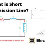
- Short transmission line – The line length is up to 60 km and the line voltage is comparatively low less than 20KV.
- Medium transmission line – The line length is between 60 km to 160 km and the line voltage is between 20kV to 100kV.
- Long transmission line – The line length is more than 160 km and the line voltage is high greater than 100KV.
A transmission line transfers electrical power from its sending end to its receiving end. Its model must predict voltage, current, real-power loss and reactive behaviour closely enough for the study being performed.


Conductor resistance causes real-power loss, while series impedance and shunt admittance affect receiving-end voltage drop. The performance of a transmission line is commonly described by efficiency and voltage regulation.
For a stated sending-end voltage, line voltage regulation compares the receiving-end voltage at no load with its value at the specified load and power factor.

A transmission line has series electrical resistance and inductance, together with shunt capacitance. These properties are physically distributed along the conductors between transmission towers.
Changes in electrical power propagate as electromagnetic waves at a speed below, but often close to, 3 × 10⁸ m ⁄ sec. Public AC systems commonly use 50 Hz or 60 Hz. The wavelength of voltage and current waves follows the equation below.


In f.λ = v, f is frequency, λ is wavelength and v is propagation velocity.
At power frequency, wavelength is much longer than most individual sections of a transmission line. Engineers can therefore use lumped approximations when their error is acceptable.
A short transmission line model usually neglects shunt capacitance. Medium-line models use a nominal π or nominal T network with lumped shunt admittance. A long transmission line model treats series impedance and shunt admittance as distributed. The kilometre and voltage boundaries in the frozen list are textbook conventions, not universal physical limits.