

- Energy Meter Definition: An energy meter is a device that measures electric energy consumption.
- Lag Adjustment in Energy Meter: Lag adjustment devices correct the phase angle between the supply voltage and pressure coil flux for accurate readings.
- Adjusting Coil Resistance: Changing the coil’s electrical resistance adjusts the lag angle, affecting the meter’s accuracy.
- Shading Bands: Moving shading bands alters the flux, which helps in adjusting the lag angle for precise measurements.
- Friction and Overload Compensation: Compensating for friction and overload ensures the meter’s accuracy and prevents issues like creeping.
In induction type energy meters, disc speed must represent active power. For the correct torque relationship, the pressure-coil flux should lag the applied voltage by about 90 degrees. Coil resistance, leakage flux and magnetic losses prevent an exact phase displacement, so a lag adjustment corrects the meter during calibration. The figure shows one arrangement:
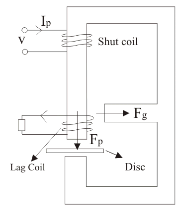
The figure shows a short-circuited lag coil with N turns on the central limb. Voltage applied to the pressure coil produces flux F, which divides into Fp and Fg. The working flux Fp crosses the disc and links the lag coil, where it induces emf El. The resulting current Il produces a compensating flux Fl. The combination of Fl and Fp sets the phase of the resultant flux that crosses the disc. Changing Fl changes that phase. Two common adjustments change the shading-circuit magnetomotive force, or mmf:
- Adjusting the circuit’s electrical resistance.
- Moving the shading bands.
These adjustments work as follows:
(1) Adjustment of coil resistance: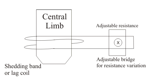
Changing the coil’s electrical resistance changes the magnitude and phase of the short-circuit current. This changes the coil’s mmf and therefore the pressure-flux phase. The adjustment must be made against a reference standard at the specified voltage, current, frequency and power factor. The coil itself should not be rewound as a routine field adjustment.
(2) Moving the shading bands changes how much central-limb flux links them. That changes the induced current, shading mmf and final phase displacement. The direction and amount of movement depend on the meter design, so the maker’s calibration procedure determines the correct position.
Friction Compensation

Friction compensation adds a small driving torque so that bearing and register friction do not cause a large error at light load. Too much compensation can cause creeping: continuous disc motion while the pressure coil is energised and no load current flows through the current coil. A common anti-creep feature uses two opposite holes or slots in the disc to disturb the eddy current path near C1. As a hole approaches the shunt-magnet pole at C1, the disturbed torque stops sustained rotation. Calibration must still confirm that the meter does not creep.
Overload Compensation
As the disc rotates, its motion through the series magnetic field induces an additional emf and eddy current. Their interaction produces a retarding, or breaking, torque that rises strongly with current and can make the meter register slowly at high load. Meter design limits this self-braking effect by keeping rated disc speed within its intended range. Accuracy tests are still required because both the driving and braking systems can introduce error:
Error caused by Driving System
- Error Due to Non SymmetricalMagnetic Circuit
An asymmetrical magnetic circuit can create an unwanted driving torque even with no load current, which can contribute to creep. - Error Due to Wrong Phase Angle
An incorrect phase displacement changes disc torque and registration, especially away from unity power factor. Causes include incorrect lag adjustment, temperature-related resistance change and supply frequency outside the meter’s rated condition. - Error Due to Wrong Magnitude of Fluxes
Incorrect voltage or current, magnetic saturation, coil faults and changed magnetic gaps can alter the working fluxes and cause registration error.


