

- Electronic DC Voltmeter Definition: An electronic DC voltmeter is defined as a device that measures direct current (DC) voltage across any two points in an electric circuit using semiconductor components.
- DC Voltage: DC voltage is a constant voltage from sources like batteries and solar cells, with no change in polarity or magnitude over time.
- Working Principle: Electronic DC voltmeters convert DC voltage to a proportional current displayed by a meter, using components like resistors and amplifiers.
- Types of Voltmeters: Types include average reading diode vacuum tube voltmeters and difference amplifier voltmeters, each with specific functions and features.
- Applications: Electronic voltmeters are used for testing circuits, measuring battery and solar panel outputs, and detecting sensor and bioelectric signals.
An electronic DC voltmeter measures direct current (DC) voltage between two points in an electric circuit. Connect it in parallel with the points under test and observe terminal polarity. Electronic instruments use input protection, range networks, buffers, amplifiers and analogue-to-digital converters. Components such as diodes protect or condition the input; transistors and amplifiers provide high input impedance and signal processing.
What is a DC Voltage?
A DC voltage has a fixed reference polarity or a zero-frequency component, but its magnitude need not remain constant. Battery terminal voltage changes with load and state of charge; solar cells vary with irradiance and temperature; DC generators can have ripple. The sign of a reading follows which lead is connected to the higher potential, not the direction of current. An inverter converts DC to alternating current (AC); a transformer may then change the AC voltage.
How does an Electronic DC Voltmeter Work?
A modern digital voltmeter applies the input to a protected, high-impedance range circuit. A buffer or amplifier presents a suitable signal to an analogue-to-digital converter, which compares it with an internal reference and sends a number to the display. A legacy analogue electronic voltmeter may instead drive a PMMC movement with current proportional to input voltage. A digital display is an electronic readout, not a meter movement. Input resistors, capacitors, protection diodes, amplifiers and the reference all contribute error and bandwidth limits.
The preserved diagrams illustrate common functions in an older electronic-voltmeter signal path:
- Voltage divider: A range network of resistors attenuates input voltage to a safe level for the next stage. Divider ratio sets the nominal range. Its equivalent input resistance loads the source, and resistor tolerance, leakage and temperature coefficient affect accuracy. A resistive divider does not provide galvanic isolation.
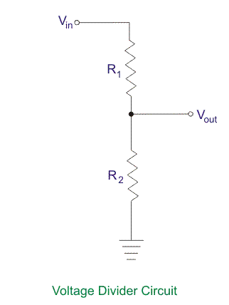
The divider and input terminals also need protection against overload, reverse polarity and transients within the meter’s stated limits. Protection must not add excessive leakage on sensitive ranges.
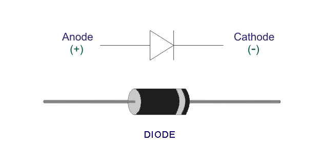
Diodes can clamp excessive input voltage or form part of a legacy rectifier stage. Their leakage, capacitance and forward characteristic can cause error. Rectification is required for many AC-voltage methods, not for an input that is already DC.
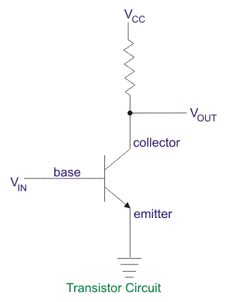
A transistor input buffer reduces source loading by presenting high input resistance. Bias current, offset voltage, drift and common-mode limits still matter, especially with high source resistance or small signals.
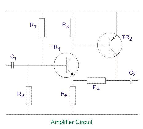
An amplifier scales a low-level or differential signal for the display or converter. Accuracy depends on gain error, offset, noise, input range, rejection of common-mode and mains-frequency signals, warm-up and calibration conditions.
Types of Electronic DC Voltmeters
Electronic voltmeters can be grouped by input architecture and readout. Legacy analogue circuits and modern digital instruments solve different measurement problems.
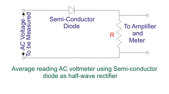
- Average reading diode vacuum tube voltmeter: This is a legacy AC-voltage circuit, despite its placement on this DC-voltmeter page. A diode rectifies AC and a PMMC movement responds to average rectified current, often with a scale calibrated for a sine-wave RMS value. A vacuum-tube buffer can provide high input resistance. Diode nonlinearity limits small-signal accuracy, and waveform error occurs for non-sinusoidal inputs. Direct DC measurement does not need the rectifying stage.
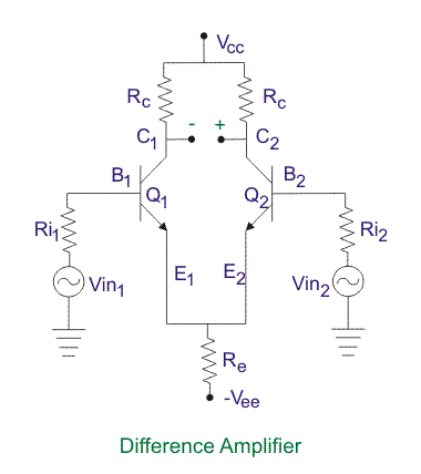
A differential-amplifier voltmeter measures the voltage between two input terminals while rejecting voltage common to both. Its permissible differential and common-mode ranges, input resistance and common-mode rejection must all suit the circuit.
A digital voltmeter uses an analogue-to-digital converter and numeric display. Integrating converters can reject mains-frequency noise, while sampling instruments can capture change over time. Range, resolution, integration time, input impedance and safety rating are model-specific. Accuracy is commonly stated as a term proportional to reading plus a term proportional to range for a defined period and temperature.
Applications of Electronic DC Voltmeters
Choose the meter, probes and method for the source impedance, voltage, environment and required uncertainty. Applications include:
- Testing supply rails, references and bias points while accounting for source loading and ground connection
- Measuring battery terminal voltage under a defined load; voltage alone may not establish state of charge
- Measuring solar-panel voltage at open circuit or a stated operating point; power also requires current at the same point
- Reading sensor and bridge outputs with suitable input bias, noise, shielding and common-mode performance
- Measuring electrostatic potentials with a specialised electrometer or non-contact probe whose input leakage and capacitance are low enough
- Measuring bioelectric signals only with patient-isolated, medically approved instrumentation and the required electrodes and filters
Conclusion
An electronic DC voltmeter measures direct current (DC) voltage between two points while drawing a small input current. Modern instruments attenuate or buffer the input, convert it to a digital value and display the result. The divider does not isolate the circuit, and input resistance can change the measured voltage. Select range, resolution, accuracy, input impedance, maximum common-mode voltage, transient category and probes from the actual task. Small signals need control of thermal EMF, noise and leakage; high-energy circuits need an appropriately rated instrument and safe procedure.


