
- AND Operation Defined: The AND operation is a fundamental digital logic gate that outputs true or 1 only when all its inputs are true or 1.
- Truth Table Use: The truth table for AND operation is a simple way to see all possible input combinations and their respective outputs, which are mostly 0 except when all inputs are 1.
- Switch Analogy: Using switches in series to represent AND logic helps visualize that the circuit only completes and outputs a signal when all switches are closed.
- Comparison to OR Operation: Unlike the OR operation, the AND operation requires all inputs to be true to output a true signal, demonstrating stricter input conditions.
- Complement Logic Understanding: Complement logic, not directly related to AND or OR operations, inverts the input signal, demonstrating the versatility of logical operations in circuits.
The AND operation combines Boolean values in digital electronics. A two-input Logical AND operation, also called a Boolean AND operation, produces 1 only when both inputs are 1. The AND operation produces 0 for every other input pair. Logic gates implement the Logical AND operation in digital circuits. A truth table lists all input combinations. In algebraic notation, Boolean AND operation uses a dot or adjacency, so Y = A·B or Y = AB. This notation resembles multiplication, but the operands are Boolean values. The two-input AND operation is shown below.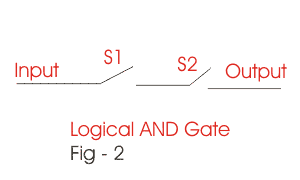
For the AND operation, input pairs 0 and 0, 0 and 1, or 1 and 0 produce Y = 0. Only 1 and 1 produces Y = 1. By comparison, the inclusive OR operation produces 1 when either input or both inputs are 1.
| INPUT | OUTPUT | |
| A | B | Y = A.B |
| 0 | 0 | 0 |
| 0 | 1 | 0 |
| 1 | 0 | 0 |
| 1 | 1 | 1 |
The output is 1 when A = 1 and B = 1. If either input is 0, the output is 0. An ideal series-switch circuit models this behaviour.
With two switches in series, the conducting path is complete only when both switches are closed. If S1 or S2 is open, current cannot reach the load. Assigning closed = 1 and open = 0 makes the four switch states follow the AND truth table. Real logic gates use defined voltage ranges rather than literal mechanical switches. This is the basis of the Logical AND operation analogy.
Boolean Complement (NOT)
| INPUT | OUTPUT |
| A | A’ |
| 0 | 1 |
| 1 | 0 |
Complement Logic is the unary NOT operation. It changes 1 to 0 and 0 to 1. Unlike AND and OR, NOT has one input. The table writes the complement of A as A’, using a prime mark after the variable.
A NOT gate implements Boolean complementation in a digital circuit. It produces the opposite logic state from its input, subject to the device’s specified input and output voltage ranges.


