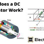
- Alternator Definition: An alternator is a machine that converts mechanical energy into alternating electrical energy using electromagnetic induction.
- Working Principle: The alternator working principle is based on Faraday’s law where motion between a conductor and a magnetic field induces an electrical current.
- Induction Process: Maximum current induction in an alternator occurs when the conductor’s motion is perpendicular to the magnetic flux lines.
- Current Alternation: In an alternator, the electrical current reverses direction with each half-turn of the rotor, simulating a complete sine wave during each rotation.
- Practical Configuration: Modern alternators typically feature a stationary armature and a rotating magnetic field, enhancing efficiency in generating three-phase AC for widespread electrical distribution.
The working principle of an alternator uses the same electromagnetic-induction law as the basic principle of DC generator. Under Faraday’s law of electromagnetic induction, changing flux linkage induces EMF. A closed circuit then allows current to flow. Relative motion between a conductor and a magnetic field provides that changing linkage in the elementary model.
To trace the working of alternator, consider one rectangular turn between opposite magnetic poles.
Loop ABCD rotates clockwise about axis a-b. After 90o, side AB, or conductor AB, is under the south pole and side CD is under the north pole. Each active side moves perpendicular to the air-gap flux, so induced EMF magnitude is at its maximum. Fleming’s right-hand rule gives the induced direction from A to B in side AB and from C to D in side CD for the motion and pole orientation shown.
After another 90-degree clockwise rotation, loop ABCD is vertical. The active sides move parallel to the field, so the ideal induced EMF in each conductor is zero. Current is also zero at that instant when the loop has no other source.
As ABCD moves from horizontal to vertical, the angle between conductor motion and the field falls from 90o to 0o. The induced EMF therefore falls from its maximum magnitude to zero. For a resistive closed loop, current follows the same shape.
After a further 90o clockwise rotation, the loop is horizontal with AB under the north pole and CD under the south pole. Fleming’s rule now gives induced current from B to A in AB and from D to C in CD.
From vertical to horizontal, induced EMF grows from zero to its opposite-polarity maximum. In a closed resistive loop, the current path is B-to-A-to-D-to-C-to-B, opposite the earlier A-to-B-to-C-to-D-to-A direction.
As the loop returns to vertical, induced EMF falls to zero and then reverses. With constant speed and a sinusoidal air-gap flux distribution, a two-pole single loop produces one sinusoidal voltage cycle per mechanical revolution. A machine with P poles produces P/2 electrical cycles per revolution, so frequency in hertz equals P times speed in rpm divided by 120.
Each rotating coil end connects to a continuous slip ring, and a stationary brush contacts each ring. Connecting a load across the brushes produces alternating load current. This is an elementary rotating-armature alternator, not the usual arrangement for a large practical machine.

The elementary model rotates the armature in a stationary field. In the usual large-machine construction of alternator, the three-phase armature winding is stationary and the magnetic field rotates. This keeps high-voltage load current out of moving contacts. A prime mover such as a turbine drives the field rotor at synchronous speed Ns. DC field excitation may reach the rotor through slip rings or a brushless excitation system.
The rotating field changes flux linkage in the stationary armature and induces three alternating phase voltages. The phase windings are arranged to produce a displacement of 120o electrical, not necessarily 120o mechanical. A connected load allows phase currents to flow, with magnitude and phase set by the generator, excitation, network and load. The three voltages remain 120 electrical degrees apart during balanced operation.