

- Rotating Magnetic Field Definition: A rotating magnetic field is created when a three-phase supply is applied to a three-phase distributed winding in a rotating machine.
- Three-Phase Supply: This supply involves three currents that are 120 degrees apart, creating a balanced system.
- Magnetic Flux Behavior: The magnetic flux produced in each phase is in phase with the currents and can be represented graphically.
- Rotation of Flux Vector: The resultant flux vector rotates with a constant value and completes a full cycle.
- Production of Rotating Magnetic Field: This rotating field is established due to the balanced supply applied to the stator winding.
In this article, we will try to understand the theory behind the production of rotating magnetic field. For that, we will first imagine one stator of an electric motor where three-phase winding is physically distributed in the stator core in such a manner that winding of each phase is separated from other by 120o in space.
Although the vector sum of three currents in a balanced three-phase system is zero at any moment, the resultant magnetic fields produced by these currents is not zero. Instead, it has a constant non-zero value that rotates over time.
The magnetic flux produced by the current in each phase can be represented by specific equations. These equations show that the flux is in phase with the current, similar to a three-phase current system.
Where, φR, φY and φB are the instantaneous flux of corresponding Red, Yellow and Blue phase winding, φm amplitude of the flux wave. The flux wave in the space can be represented as shown below.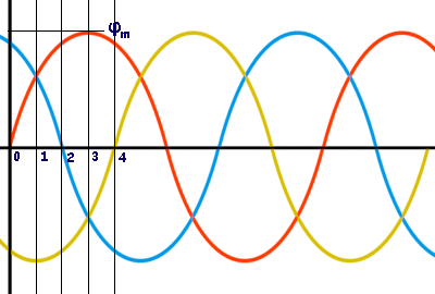
Now, on the above graphical representation of flux waves, we will first consider the point 0.
Here, the value of φR is 
The value of φY is 
The value of φB is 
The resultant of these fluxes at that instant (φr) is 1.5φm which is shown in the figure below.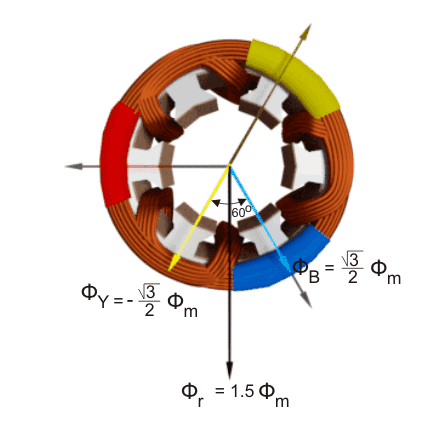
Now, on the above graphical representation of flux waves, we will consider the point 1, where ωt = π / 6 or 30o.
Here, the value of φR is 
The value of φY is 
The value of φB is 
The resultant of these fluxes at that instant (φr) is 1.5φm which is shown in the figure below. here it is clear thet the resultant flux vector is rotated 30o further clockwise without changing its value.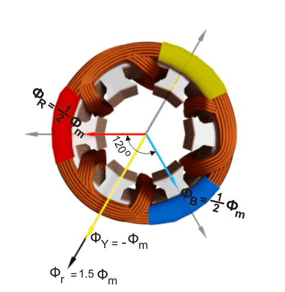
Now, on the graphical representation of flux waves, we will consider the point 2, where ωt = π / 3 or 60o.
Here, the value of φR is 
The value of φY is 
The value of φB is 
The resultant of these fluxes at that instant (φr) is 1.5φm which is shown in the figure below. here it is clear thet the resultant flux vector is rotated 30° further clockwise without changing its value.
Now, on the graphical representation of flux waves, we will consider the point 3, where ωt = π / 2 or 90o.
Here, the value of φR is 
The value of φY is 
The value of φB is 
The resultant of these fluxes at that instant (φr) is 1.5φm which is shown in the figure below. here it is clear thet the resultant flux vector is rotated 30o further clockwise without changing its value.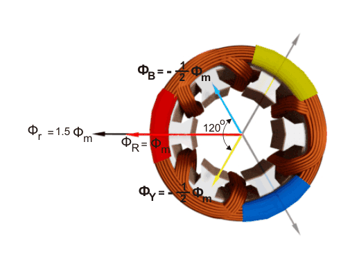
This demonstrates that a balanced supply applied to a three-phase stator winding creates a rotating magnetic field in space.


