

- Phase Sequence Indicator Definition: A phase sequence indicator is a device used to determine the phase order of a three-phase electrical supply.
- Types of Indicators: There are two types—rotating type and static type, each with a distinct working principle.
- Rotating Type Working Principle: It operates on induction motor principles, using a rotating magnetic field to move an aluminum disc and indicate phase sequence.
- Static Type Working Principle: It uses lamps that vary in brightness depending on the phase sequence, with some variants using capacitors and neon lamps.
- Determining Phase Sequence: These indicators help identify if the phase sequence is RYB or reversed, crucial for the correct operation of three-phase systems.
In a three phase system, phase conductors may be labelled R, Y and B, or L1, L2 and L3. A phase sequence indicator determines the temporal order in which the three phase voltages reach the same point in their cycles.
An induction motor connected to a fixed terminal arrangement turns in one direction for one phase sequence.
Swapping any two supply conductors reverses the rotating magnetic field and the motor direction. Clockwise rotation is not an inherent property of the letters RYB because actual shaft direction also depends on the motor winding and terminal connections.
Two common types of phase sequence indicators are:
- Rotating type
- Static type.
Each type uses a different indication method.
Rotating Type Phase Sequence Indicators
A rotating indicator works on the induction-motor principle. Its three coils are connected to the three marked test terminals. The three-phase supply produces a rotating magnetic field, which induces an EMF in the movable aluminium disc. The induced disc current interacts with the field and produces torque.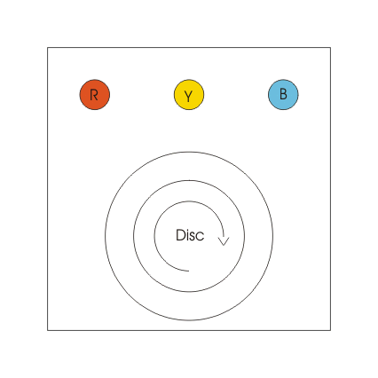
The induced EMF produces eddy current in the aluminium disc. Reversing any two phases reverses the field and disc rotation. Read the result from the direction arrow or sequence marking on the instrument. A clockwise indication represents RYB only when the leads are connected to the matching marked terminals and the instrument labels that direction as RYB.
Static Type Phase Sequence Indicators
The arrangement of a static indicator is shown below: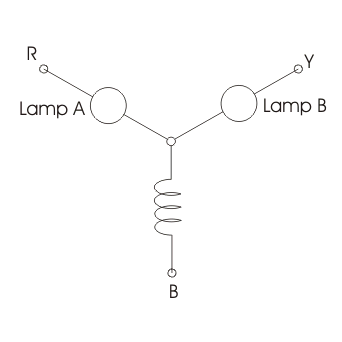
In the illustrated connection, one sequence makes Lamp B brighter than Lamp A, and the reverse sequence swaps their brightness. The lamp labels apply to this circuit and terminal connection.
Assume the sequence is RYB. Mark the line-to-line voltages as Vry, Vyb and Vbr, as shown in the diagram. The phasor relation is: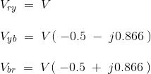
For a balanced supply, Vry=Vbr=Vyb=V in magnitude. Kirchhoff’s current law at the floating junction requires the algebraic sum of the three branch currents to equal zero. The circuit equations are:
For the ideal component values used in the diagram, the calculated ratio of Ir to Iy is 0.27.
Lamp A therefore receives about 27 percent of Lamp B’s voltage for the assumed RYB connection and glows more dimly. Reversing the phase sequence swaps the relative lamp voltages and brightness.
A related static indicator replaces the inductor with a capacitor, as shown below.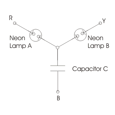
Each neon lamp has a series resistor to limit current. In the illustrated terminal arrangement, RYB lights Lamp A and the reverse sequence lights Lamp B. Because a phase-sequence test is performed on an energised three-phase supply, use a properly rated enclosed indicator and follow its connection and safety instructions.


