

- Owens Bridge Definition: Owens Bridge is defined as an AC bridge used to measure inductors over a wide range by using standard capacitors and variable resistors.
- Circuit Components: The circuit includes an inductor with resistance, pure resistor, pure capacitor, and a combination of variable resistor and capacitor.
- Working Principle: It measures inductance in terms of capacitance, allowing calculations using a specific balance equation.
- Modified Circuit: The modified Owens Bridge uses a valve voltmeter and AC and DC sources to measure incremental inductance.
- Advantages: Owens Bridge is simple and frequency-independent, making it useful for a wide range of inductance measurements.
Hay, Maxwell and Anderson already cover much inductor work. Hay’s bridge suits quality factor above 10. Maxwell’s bridge suits Q from about 1 to 10. Anderson bridge covers a wide L span. Owens Bridge is the Owen L-C bridge used when you want that wide L span in terms of a standard capacitor, including incremental inductance with DC bias.
Owen’s network measures a wide span of inductance against capacitance. That is the job of Owens Bridge on this page.
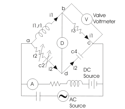
Like Hay and Maxwell it is an AC four-arm bridge. A standard capacitor, the unknown coil and variable resistors take the arms. An AC source drives the bridge. The Owen’s bridge circuit is below.
Theory of Owen’s Bridge

An Owen’s bridge circuit is given below.
The AC source is connected at a and c. Arm ab is the unknown coil, drawn as r1 in series with l1. Arm bc is a non-reactive electrical resistance r3. At null the same current i1 flows through ab and bc; that is the current in those two arms.
Arm cd is drawn as a lossless capacitor. Arm ad holds a variable resistor and a capacitor. The detector sits between b and d. The null reads unknown L from the standard C. The algebra is next.
Here l1 is the unknown inductance and c2 is the variable standard capacitor.
At null the AC-bridge product rule holds:
Substitute z1, z2, z3 and z4 to get
Split real and imaginary parts to get l1 and r1:
Iron-cored coils need a DC bias if you want incremental inductance. The modified Owens Bridge circuit does that job:
A valve (vacuum-tube) voltmeter sits across r3. AC and DC feed the network in parallel. A choke keeps AC out of the DC supply. A blocking capacitor keeps DC out of the AC supply. An ammeter in series with the battery reads the DC. The voltmeter ignores DC, so its reading across resistance r3 is the AC component.
At null the incremental inductor is l1 = r2r3c4
also inductor
Therefore incremental permeability is
N is turns. A is the flux-path area. l is the flux-path length. l1 is the incremental inductance.
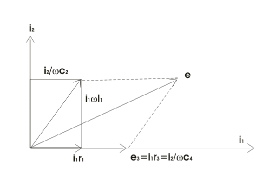
Label the drops on ab, bc, cd and ad as e1, e3, e4 and e2 as in the figure. Those labels match the phasor sketch.
The most lagging current i1 is the reference. Current i2 is drawn at 90° to i1. The drop on inductor l1 is at 90° to i1. The drop on capacitor c2 is at 90° to i2. At null e1 = e2. The source voltage e is the phasor sum of e1, e2, e3 and e4.
Advantages of Owen’s Bridge
- The expression for inductor l1 is simple and has no frequency term.
- The same network covers a wide span of inductance.
Disadvantages of Owen’s Bridge
- The variable standard capacitor is costly. Textbook figures often put its working accuracy near one percent.
- Higher measured Q needs a larger standard capacitor, which raises the cost of the set.


