

- Resistance Temperature Detector Definition: An RTD is defined as a device that measures temperature by detecting changes in electrical resistance.
- Construction Details: RTDs consist of metal wires coiled on a mica frame, enclosed in a protective sheath to minimize unwanted resistance changes.
- Signal Conditioning Explained: Accurate temperature readings are obtained by conditioning signals through a bridge circuit that compensates for minor resistance variations.
- Wire Configurations: Three types of RTD setups—two-wire, three-wire, and four-wire—offer varying degrees of accuracy by addressing the impact of wire resistance.
- Self-Heating Limitation: One of the primary limitations of RTDs is the potential for self-heating, which can skew temperature measurements if not properly managed.
What is an RTD (Resistance Temperature Detector)?
A Resistance Temperature Detector, also called a Resistance Thermometer or RTD, is a passive sensor whose electrical resistance changes predictably with temperature. Instrumentation measures that resistance and applies the sensor’s calibration curve. An RTD can provide high accuracy and repeatability, but suitability also depends on range, response time, vibration, wiring and installation. Alternatives include a thermocouple or a thermistor.
The displayed polynomial is a general way to approximate how metal resistance changes with temperature. Standard platinum RTDs use defined Callendar-Van Dusen coefficients instead of arbitrary constants:
Here Rt and R0 are the resistance values at toC and reference t0oC. The coefficients depend on the material and calibration convention. For an IEC Pt100, the nominal resistance is 100 Ω at 0°C and the standard specifies the polynomial coefficients.
A first-order expression can approximate resistance over a limited temperature interval. Its error grows when the interval widens, so precision work uses the full standard relation or a calibrated table:


RTD elements can use platinum, nickel or copper. Each material has its own nominal resistance, temperature coefficient, usable range, stability and standardisation.
Temperature limits are not fixed only by the metal. Element construction, sheath, lead insulation and tolerance class also matter. IEC platinum elements may cover ranges up to 850oC in some constructions, while a finished probe can have lower limits. Copper and nickel probes likewise do not have universal limits of 120oC and 300oC. A standard Pt100 changes by about 0.385 Ω/°C near 0°C.
The ratio R100/R0 relates the resistance values at 100°C and 0°C, so it reflects the temperature coefficient. Material composition, strain and manufacture can shift the characteristic, so standards specify nominal values and tolerance classes.
Construction of Resistance Temperature Detector or RTD
A wire-wound RTD uses fine resistance wire supported by an insulating former such as ceramic, glass or mica. Another common design deposits a thin platinum film on a ceramic substrate. An industrial probe places the element in a protective sheath selected for the process, pressure, vibration and chemical environment.
The element support should limit strain because mechanical stress can change resistance independently of temperature. The assembly must also provide electrical insulation and a controlled thermal path to the process.
A sheath protects the element, but its diameter, fill material and contact with a thermowell affect response time. Probe maintenance while a plant operates is permitted only when the installation and site procedure are designed for safe removal. The figure shows one wire-wound industrial RTD construction.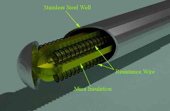
Signal Conditioning of RTD
An RTD needs excitation and resistance measurement. The circuit must control errors from lead resistance, reference accuracy, current-source mismatch, ADC offset, noise, nonlinearity and self-heating.
A bridge or ratiometric circuit can drive the RTD with a known electric current and measure its voltage relative to a reference resistor. The measured resistance is converted to temperature with the specified calibration relation. The figures show common connections.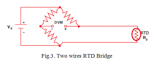
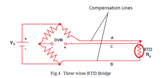
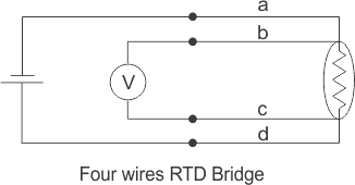
In a two-wire connection, both lead resistances add directly to the measured RTD resistance. A three-wire circuit estimates or cancels much of that error only when its lead resistances and measurement circuitry satisfy the design assumptions.
In a three-wire RTD bridge, matched lead resistances can appear in opposing parts of the measurement and cancel to first order. Other three-wire circuits use matched excitation currents. A four-wire Kelvin connection uses two current leads and two high-impedance sense leads to measure voltage drop at the sensor with negligible lead contribution. Neither bridge output nor RTD resistance is exactly proportional to temperature over the full range, so conversion and calibration remain necessary.
Expressions for a Three-Wire RTD Circuit
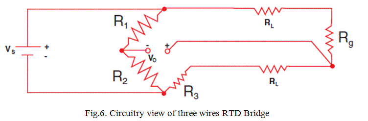
Given VS and VO, the bridge equation can be solved for Rg and then converted to temperature. The shown derivation assumes R1 = R2: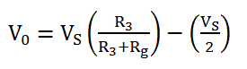
When R3 = Rg, VO = 0 for an ideal balanced bridge. Solving the equation gives the displayed expression for Rg.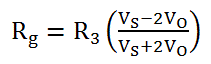
That expression assumes lead resistance RL = 0. Including RL changes the inferred Rg as shown:
The remaining RL error depends on RL matching and the exact bridge connection. The third lead C enables compensation; it does not guarantee zero lead error when the leads or circuit are mismatched.
Video Presentation on Resistance Temperature Detector or RTD
Limitations of RTD
RTD excitation produces I2R power in the element. The resulting self-heating raises the sensor above the process temperature and creates measurement error. The electric current through the RTD must be low enough for the required error limit. The allowable current depends on resistance, duty cycle, probe construction and heat transfer to the process.


