

- De Sauty Bridge Definition: De Sauty Bridge is defined as a method for comparing the values of two capacitors by balancing a bridge circuit.
- Working Principle: It operates by adjusting resistances to balance the voltage drops across capacitors, ensuring accurate comparison.
- Balance Achievement: To achieve balance, the values of specific resistors are adjusted without altering other elements in the bridge.
- Advantages and Limitations: The De Sauty Bridge is simple and easy to use but provides inaccurate results for capacitors with dielectric losses.
- Grover’s Modification: Adding resistances to the bridge can account for dielectric losses, improving accuracy for imperfect capacitors.

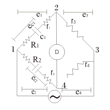
The De Sauty bridge compares an unknown capacitor with a known standard. The basic circuit assumes both capacitors are lossless, so it is best suited to low-loss air capacitors. The circuit of De Sauty’s Bridge is shown below.
The diagram uses a battery symbol between supply terminals 1 and 4, but the unknown capacitor c1 needs alternating excitation so steady capacitive current i1 can flow. One bridge branch contains the unknown capacitor and a non-inductive resistor; the opposite branch contains the standard capacitor and a second non-inductive resistor. A null detector is connected across the other diagonal.
The balance equation relates c1 to the standard capacitance and the resistance ratio.
At balance,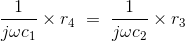
The unknown capacitance is therefore
Balance is obtained by adjusting either r3 or r4 until the detector current is zero. The result is independent of excitation frequency for ideal capacitors and non-inductive resistors, but dielectric loss can prevent a true null.
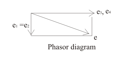
The phasor diagram for the ideal De Sauty bridge is shown below:
Let the branch current be i1. Mark the capacitor voltage as e1, the voltage drop across resistor r3 as e3, the corresponding resistor voltage as e4 and the standard-capacitor voltage as e2. At balance, detector current is zero and the two detector nodes have equal potential. The corresponding drops satisfy e1 = e2 and e3 = e4.

Take e3 (or e4) as the reference phasor. The capacitive voltages e1 and e2 are at right angles to their respective branch currents, while e1 (or e2) and the resistor voltage add to give the supply voltage. For an ideal capacitor, current leads capacitor voltage by 90o.
The bridge is simple and its balance equation is easy to use. Its main limitation is dielectric loss: capacitors with different loss angles generally cannot satisfy both magnitude and phase balance. The basic bridge should therefore compare capacitors whose losses are negligible.
Grover’s modification of the De Sauty’s bridge represents capacitor loss and adds adjustable series resistance so both balance conditions can be approached. The modified circuit is shown below:
The internal electrical resistances r1 and r2 represent the series losses of the unknown and standard capacitors. External resistances R1 and R2 are connected in the corresponding capacitor arms. The aim is to determine the unknown capacitance c1 by comparison with the standard capacitor in the other arm, as in the basic De Sauty’s bridge. At balance, the complex voltage-drop equation is
Separating and solving the real and imaginary conditions gives
This is the capacitance and resistance-ratio condition.
The phasor diagram can also be used to relate the two dissipation factors, as shown below.
Let δ1 and δ2 be the loss angles of capacitors c1 and c2. In the series-loss model, tan(δ1) = ωc1r1, and tan(δ2) = ωc2r2.
From equation (1),
Multiplying both sides by ω gives
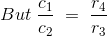
The final relation between dissipation factors is
One dissipation factor can be estimated if the other is known. This modified bridge is not preferred for precise loss measurement because the result depends on the difference between resistance terms and is sensitive to adjustment error.


