

- Capacitor Definition: A capacitor is a device that stores energy in an electric field, created by two metal plates separated by a dielectric material.
- Series Capacitance: In a series connection, capacitors decrease the total capacitance, which can be calculated using the formula 1/C = 1/C1 + 1/C2 + … + 1/Cn.
- Parallel Capacitance: In a parallel connection, capacitors increase the total capacitance, calculated by adding their individual capacitances, C = C1 + C2 + … + Cn.
- Charge and Voltage in Series and Parallel: In series, the charge across each capacitor is the same, while in parallel, the voltage across each capacitor is the same.
- Applications of Capacitors: Series and parallel capacitor connections are crucial for achieving specific capacitance values needed in different electronic devices and power systems.
Capacitor in Series
Let’s connect multiple capacitors in series with a voltage of V volts applied across them.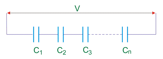
Let’s consider the capacitance of the capacitors as C1, C2, C3…….Cn, and the equivalent capacitance of the series combination as C. The voltage drops across capacitors are V1, V2, V3…….Vn.

Now, if Q coulomb be the charge transferred from the source through these capacitors, then,
Since the charge accumulated in each capacitor and I entire series combination of capacitors will be same and it is considered as Q.
Now, equation (i) can be written as,
Capacitors in Parallel
A capacitor stores energy in its electric field, known as electrostatic energy. To store more electrostatic energy, a capacitor with higher capacitance is needed.
A capacitor consists of two metal plates connected in parallel, separated by a dielectric medium like glass, mica, or ceramics. The dielectric provides a non-conducting barrier that holds the charge, and the ability of the capacitor to store charge is called capacitance. When a voltage source is connected across the plates of the capacitor a positive charge on one plate, and negative charge on the other plate get deposited. The total amount of charge (q) accumulated is directly proportional to the voltage source (V) such that,
Where, C is proportionality constant i.e. capacitance. Its value depends upon physical dimensions of the capacitor.
Where ε = dielectric constant, A = effective plate area and d = space between plates.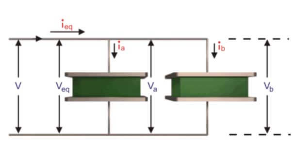
To increase the capacitance value of a capacitor, two or more capacitors are connected in parallel as two similar plates joined together joined together, then their effective overlapping area is added with constant spacing between them and hence their equivalent capacitance value becomes double (C ∝ A) of individual capacitance. The capacitor bank is utilized in various manufacturing and processing industries incorporates capacitor in parallel, so to provide a capacitance of desired value as required by regulating the connection of capacitors connected in parallel and thus it is utilized efficiently as a static compensator for the reactive power balance in power system compensation. When two capacitors are connected in parallel then the voltage (V) across each capacitor is same i.e. (Veq = Va = Vb) and current( ieq ) is divided into two parts ia and ib. As it is known that 
Putting the value of q from equation (1) in the above equation,
The later term becomes zero (as capacitor’ capacitance is constant). Therefore,
Applying Kirchhoff’s Current Law at the incoming node of the parallel connection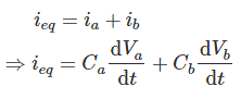
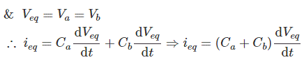
Finally we get,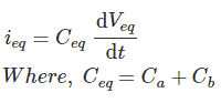
Hence, whenever n capacitors are connected in parallel the equivalent capacitance of the whole connection is given by following equation which resembles similar to the equivalent resistance of resistors when connected in series.
Method of Finding Expression of Equivalent Capacitance of Parallel Capacitor
Let us connect n number of capacitors in parallel, across a voltage source of V volt.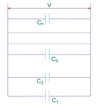
Let us consider the capacitance of the capacitors are C1, C2, C3…..Cn, respectively and equivalent capacitance of the combination of the capacitor is C. As the capacitors are connected in parallel, like current charge in each capacitor will be same. Total charge of the parallel combination, will be divided in each capacitor according to it’s capacitance value but voltage across each capacitor will be same and at steady state condition it is exactly equal to the applied voltage.
Where,Q1, Q2, Q3,…….Qn are the charge of capacitor C1, C2, C3….. Cn respectively.
Now equation (2) can be written as,


