

- Arc Suppression Coil Definition: An arc suppression coil, also known as a Petersen coil, is an inductive coil used to neutralize the capacitive charging current in underground power networks during an earth fault.
- Purpose and Function: The coil reduces the large capacitive charging current during an earth fault by creating an opposite inductive current.
- Working Principle: The inductive current generated by the coil cancels out the capacitive current, preventing arcing at the fault point.
- Capacitive Current in Underground Systems: Underground cables have a continuous capacitive current due to the dielectric insulation between the conductor and the earth.
- Inductance Calculation: The inductance of the Petersen coil is adjusted to match the capacitive current in the system, often using a tap-changing arrangement.
The voltages of a three phase balanced system is shown in figure – 1.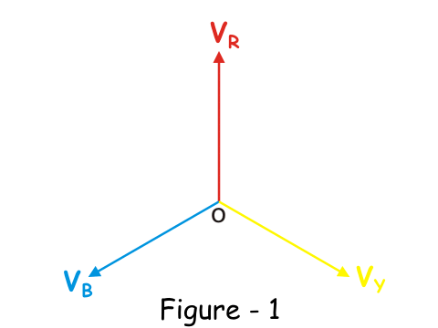
In underground high voltage and medium voltage cable networks, each phase has capacitance between the conductor and the earth, leading to a continuous capacitive current. This current leads the phase voltage by 90 degrees as shown in figure – 2.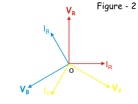
If an earth fault occurs in the yellow phase, the voltage of the yellow phase to ground becomes zero. The system’s neutral point shifts to the tip of the yellow phase vector. Consequently, the voltage in the healthy phases (red and blue) increases to &sqrt;3 times the original value.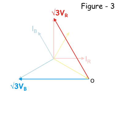
Naturally, the corresponding capacitive current in each healthy phase (red and blue) becomes &sqrt;3 of the original as shown in figure-4, below.
The vector sum that is resultant of these two capacitive current now will be 3I, where I is taken as rated capacitive current per phase in the balanced system. That means, at healthy balanced condition of the system, IR = IY =
IB = I.
This is illustrated in the figure- 5 below,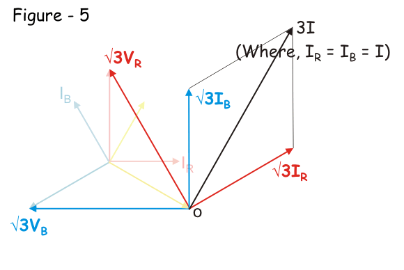
This resultant current then flows through the faulty path to the earth as shown below.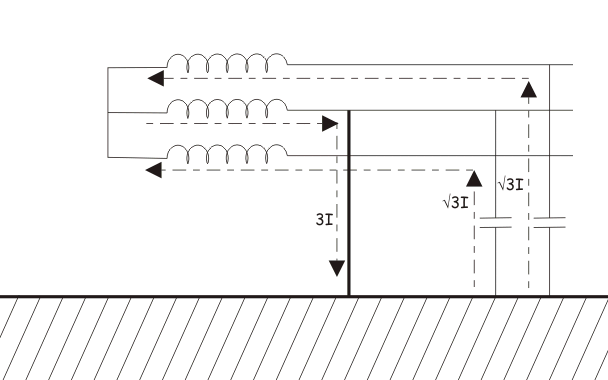
Now, if we connect one inductive coil of suitable inductance value (generally iron core inductor is used) between star point or neutral point of the system and ground, the scenario will be entirely changed. At faulty condition, the current through the inductor just equal and opposite in magnitude and phase of that of capacitive current through the faulty path. The inductive current also follow the faulty path of the system. The capacitive and inductive current cancels each other at the faulty path, hence there will not be any resultant current through the faulty path created due to capacitive action of the underground cable. The ideal situation is illustrated in the figure below.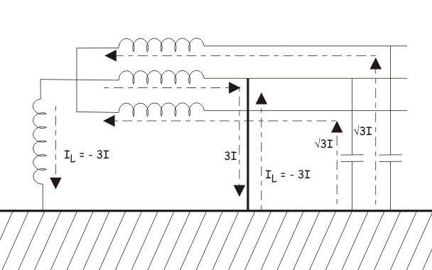
This concept was first implemented by W. Petersen in 1917, that why the inductor coil is used for the purpose, called Petersen Coil.
The capacitive component of the fault current is high in the underground cabling system. When earth fault occurs, the magnitude of this capacitive current through the faulty path becomes 3 times more than rated phase to earth capacitive current of healthy phase. This causes significant shifting of zero crossing of current away from zero crossing of voltage in the system. Due to presence of this high capacitive current in the earth fault path there will be a series of re-striking at fault location. This may lead unwanted over voltage in the system.
The inductance of the Petersen Coil is selected or adjusted at such value which causes the inductive current which can exactly neutralize the capacitive current.
Let us calculate the inductance of Petersen Coil for a 3 phase underground system.
For that let us consider capacitance between conductor and earth in each phase of a system, is C farad. Then the capacitive leakage current or charging current in each phase will be
So, the capacitive current through the faulty path during single phase to earth fault is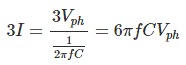
After fault, the star point will have phase voltage as the null point is shifted to fault point. So the voltage appears across the inductor is Vph. Hence, the inductive current through the coil is
Now, for cancellation capacitive current of value 3I, IL must have same magnitude but 180o electrically apart. Therefore,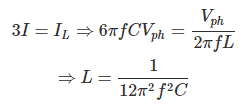
When the design or configuration of the system changes, such as length, cross-section, thickness, or insulation quality, the inductance of the coil must be adjusted. Therefore, Petersen coils often have a tap-changing arrangement.

")

: What is it?")