- Transient Stability Definition: Transient stability is the power system’s ability to return to a stable state after significant disturbances like faults or sudden changes in load.
- Swing Equation: The swing equation helps determine how changes in load affect a generator’s stability by analyzing the dynamics between mechanical and electromagnetic forces.
- Importance of Stability: Maintaining transient stability is crucial for preventing system failures and ensuring reliable power delivery.
- Instability Consequences: Without proper transient stability, power systems can experience failures, leading to blackouts and other reliability issues.
- Stability Assessment: Initial studies focus on the system’s response to the first swing post-disturbance to predict its ability to regain and maintain stability.
Transient rotor-angle stability is the ability of interconnected synchronous machines to remain in synchronism after a severe disturbance, such as a short circuit, line trip or rapid change in generation or load. A fault changes electrical power transfer and can cause machines in the power generation system to accelerate or decelerate relative to one another.
First-swing behaviour is an important part of transient assessment, but stability during the first swing does not prove that later swings are stable or adequately damped. The required simulation period depends on the disturbance, controls and study criteria. The swing equation is the basic rotor-motion model used in a synchronous-machine power system study.
Swing Equation for Determining Transient Stability
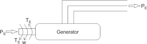 To derive the swing equation, consider a synchronous generator with mechanical shaft input PS and mechanical torque TS. The rotor turns close to synchronous angular speed ω. The generator develops electromagnetic torque TE and delivers electrical power PE.
In steady state, neglecting losses, mechanical input power equals electrical output power and rotor speed is synchronous. The load angle δ is the rotor electrical angle relative to the synchronously rotating reference associated with the stator magnetic field. Power is generally a nonlinear function of δ; in the classical lossless model, PE = Pmax sin δ.
A disturbance makes mechanical and electrical torque unequal, so the rotor accelerates or decelerates relative to the synchronous reference. This motion is a power swing, but a swing alone does not mean the system is unstable. The swing equation relates the accelerating power to the second derivative of rotor angle.
With the page’s notation, accelerating power is PS – PE. A sudden increase in electrical output makes PE greater than PS until controls or motion restore balance, so accelerating power is negative and the rotor decelerates. If PS exceeds PE, the rotor accelerates. The governing sign relation is:
The accelerating torque is mechanical torque minus electromagnetic torque:
Near synchronous speed, power equals torque multiplied by angular speed, which gives the displayed relation:
Here I denotes moment of inertia, not electric current. The mechanical relation is T = Iα, so accelerating power is approximately Iωsα.
Writing M = Iωs gives an inertia coefficient for this form of the equation.
If θ is rotor angle in a stationary frame and δ is its angle in a synchronously rotating frame, the correct relation is θ = ωst + δ, or dθ/dt = ωs + dδ/dt. The following legacy image omits dθ/dt on its left side.
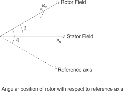
Taking the second derivative of the corrected angle relation gives:
The angular acceleration is therefore: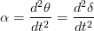
Substitution gives the undamped swing equation in the page’s M notation: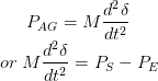
For a classical lossless single-machine-to-infinite-bus model with constant voltage magnitudes, electrical power is:
Substituting that power-angle relation gives: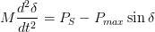
This simplified swing equation supports an introductory transient stability in power system analysis. Practical studies use explicit units or per-unit inertia, include damping and controls as required, and simulate the network and machine equations over the study period.