

- Oscilloscope Definition: An oscilloscope is defined as a device used to display the graph of an electrical signal as it varies with time.
- Measurement of Voltage: Voltage is measured by determining the peak-to-peak amplitude on the oscilloscope, showing the difference between the maximum and minimum points.
- Measurement of Current: Current is measured indirectly using probes or resistors with an oscilloscope, applying Ohm’s Law.
- Measurement of Frequency: Frequency is measured by analyzing the frequency spectrum of a signal, calculating the cycles per second.
- Automatic Voltage Measurement: Oscilloscopes can automatically measure voltage by identifying zero or peak voltage points.
An oscilloscope displays a signal against time, making it possible to inspect amplitude, timing, noise and transient behaviour in an electrical field. Its vertical system measures voltage, while its horizontal time base shows when signal events occur. Digital models can calculate many waveform values automatically, but probe choice, scaling, bandwidth, sample rate and grounding still determine whether the result is valid.
Voltage Measurement
An oscilloscope input measures voltage between its signal and reference connections. Other quantities, including current and resistance, require a transducer or a known circuit relationship.
State which waveform quantity is required. Peak-to-peak voltage is the difference between maximum and minimum values. Peak voltage is measured from a stated reference, mean voltage is the time average and RMS voltage represents heating-equivalent magnitude under the meter’s stated calculation conditions. For any voltage measurement, include the probe attenuation in the channel setting and keep the signal within the probe and input ratings. A correctly rated attenuating or differential probe extends the usable range; an improvised divider may not meet bandwidth or safety requirements.
Method to Measure Voltage
- Choose a probe with suitable voltage rating, attenuation, bandwidth and reference arrangement. On an earth-referenced bench oscilloscope, connect a standard probe’s reference lead only to earth potential. Use a rated differential or isolated system when neither test point is at earth.
- Set the channel attenuation to match the probe, select suitable coupling, centre the waveform and adjust volts per division, time per division and trigger level for a stable display. Read vertical divisions and multiply by volts per division, or select the required automatic measurement and confirm its reference levels and gate.
Current Measurement
A voltage-input oscilloscope needs a current-to-voltage device. A known shunt made from suitable resistors develops a voltage proportional to current. Clamp-on probes provide isolation from the conductor and may use a current transformer for AC, a Hall sensor for AC and DC, or a Rogowski coil for changing current.
Method to Measure Current
- For a shunt measurement, choose resistance, power rating, pulse-energy rating, inductance and tolerance so the inserted component does not disturb or overheat in the circuit. Measure its differential voltage with a probe system rated for both differential and common-mode voltage.
- Divide the measured shunt voltage by its known resistance. For a current probe, enter or verify its volts-per-ampere scaling, degauss and zero it when the manufacturer requires, then stay within current and bandwidth ratings.
For a resistive shunt, Ohm’s Law gives: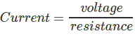
Frequency Measurement
In a time-domain display, frequency is found from the period of a repetitive waveform: frequency equals one divided by period. A spectrum or FFT view is a separate way to inspect frequency components. The highest useful frequency depends on the oscilloscope, probe, sample rate, record length and required accuracy. Rise-time measurement describes edge speed, not frequency by itself.
Method to Measure Frequency
- Set vertical sensitivity so the waveform uses several divisions without clipping, and set a stable trigger on a repeatable edge.
- Adjust time per division to show at least one complete cycle. Showing several cycles and averaging multiple periods can reduce cursor-placement error.
- Measure the horizontal divisions between equivalent points on successive cycles, such as rising-edge crossings at the same level.
- Multiply divisions by seconds per division to obtain period T, then calculate f = 1/T in hertz. On a digital oscilloscope, compare cursor and automatic frequency readings and make sure the acquisition contains enough cycles for the selected algorithm.




