- Signal Flow Graph Definition: A signal flow graph simplifies control system diagrams by using nodes and branches instead of blocks and summing points
- Transmittance: In signal flow graphs, the transfer function is called transmittance, shown by the branches connecting the nodes.
- Rules for Drawing: Signals follow the direction of the arrows on branches, and the input signal at a node is the sum of all incoming signals.
- Calculating Transfer Function: Calculate node inputs to find the overall relationship between input and output, then use this to determine the transfer function.
- Mason’s Gain Formula: This formula helps determine the overall transmittance of the signal flow graph, using path transmittances and graph determinants.

A signal flow graph of a control system is a directed graph of the same linear relations as a block diagram. Nodes stand for signals. Branches replace blocks, summing points and take-off points.
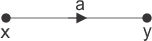
The gain of a branch is called transmittance in a signal flow graph. The equation y = Kx is one gain drawn as a block.
The signal-flow graph of that same relation uses node x as the input, node y as the output and a branch transmittance (drawn as a) equal to that gain.
Rules for Drawing Signal Flow Graph
- The signal travels along a branch only in the direction of that branch’s arrow.
- The output of a branch is the product of its transmittance and the signal at the node where the branch starts.
- The signal at a node is the sum of all signals arriving on incoming branches.
- That node signal then leaves on every outgoing branch.
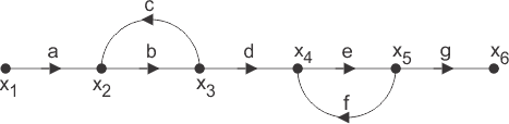
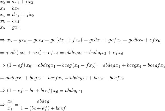
Simple Process of Calculating Expression of Transfer Function for Signal Flow Graph
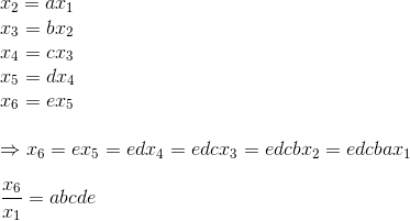
- First, write the signal at each node. Sum the products of each incoming transmittance and the variable at the tail of that branch.
- Those node equations relate the node variables to each transmittance. There is one independent equation for each dependent node.
- Solving those equations gives the output node in terms of the input node of the signal flow graph of control system.
- The overall transfer function is that output expression divided by the input node variable.
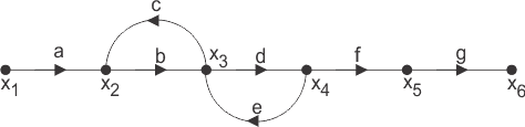
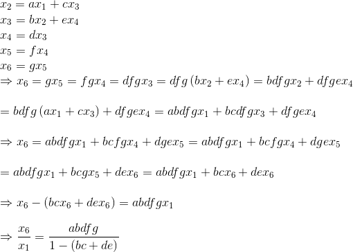

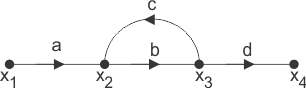

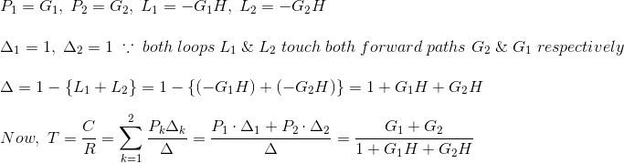
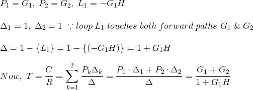
If P is the forward-path transmittance between the input node and the output node, and L1, L2 are the loop transmittances of the first and second loops, then the overall transmittance of the first signal flow graph of control system is
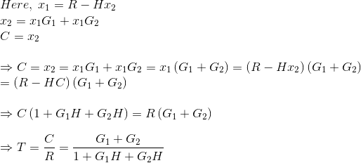
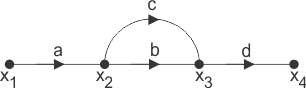
The overall transmittance of the second graph is found the same way.

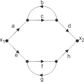
The figure above has two parallel forward paths. The overall transmittance of that signal flow graph of control system is then the sum of those two forward-path transmittances after each path’s loops are included.
Each of those parallel paths has one loop attached to it, so the forward transmittances are
The overall transmittance of the signal flow graph is then
Mason’s Gain Formula

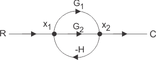
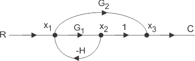
The overall transmittance or gain of a signal flow graph in a control system is given by Mason’s Gain Formula.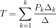
Pk is the forward-path transmittance of the kth path from a chosen input node to an output node. When tracing Pk no node is visited more than once.
Δ is the graph determinant. It is built from closed-loop transmittances and from products of non-touching loops.
Δ = 1 – (sum of all individual loop transmittances) + (sum of loop transmittance products of all possible pair of non-touching loops) – (sum of loop transmittance products of all possible triplets of non-touching loops) + (……) – (……)
Δ k is the cofactor for that path. It keeps only the closed loops that do not touch the forward path under consideration.
The path factor Δk for the kth path equals the graph determinant of the graph that remains after the Kth path is erased.
The same formula gives the overall transfer function after a block diagram of control system is redrawn as an equivalent signal flow graph. The block diagram below is the worked case.