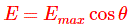
- Inverse Square Law Definition: The inverse square law states that Illuminance at a point decreases with the square of the distance from the light source.
- Luminous Intensity: This term represents the strength of the light emitted from a source in a specific direction.
- Cosine Law of Illuminance: Illuminance on a plane is proportional to the cosine of the angle at which light hits the surface.
- Impact of Angle: The angle of light incidence affects the Illuminance, with maximum Illuminance when light hits perpendicular to the surface.
- Laws of Illumination: These laws help us understand and calculate how light behaves in different scenarios, including varying distances and angles.
The Inverse-Square Law of Illuminance
For a point source and a small receiving surface normal to the incident direction, illuminance E is directly proportional to the source’s luminous intensity in that direction and inversely proportional to the square of distance d. The relationship assumes no obstruction or material attenuation between source and surface.
I is the luminous intensity in the direction from the source to the receiving point, measured in candelas. E is measured in lux.

Consider a point source with luminous intensity I in the direction shown. Spheres centred on the source provide surfaces at different radii.
The figure labels the distances r1 and r2. A small normal surface at r1 has area dA1, while the corresponding surface at r2 has area dA2.
Both areas dA1 and dA2 subtend the same solid angle Ω and therefore contain the same element of luminous flux Φ when absorption, scattering and obstruction are neglected.
The farther area dA1 at r1 is smaller than dA2 at r2. Area subtended by a fixed solid angle grows with the square of radius, so the same flux spread over the larger area produces lower illuminance.

The solid angle for each small normal surface is:
The illuminance at the first distance is:
The illuminance at the second distance is:
Equation (i) gives:
Substitute this result into equation (iii):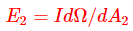


This is the inverse-square relationship for a point source and a normal receiving surface.
Doubling distance reduces direct illuminance to one quarter when the source intensity in that direction stays constant.
A finite source can be treated as a point only in its far field, where its dimensions are small compared with distance and the required error limit is met.
For an extended source in the near field, calculate and sum the contributions from source elements or use a validated near-field photometric model.
The Cosine Law of Illuminance
When a small receiving plane is tilted, direct illuminance includes the cosine of the incidence angle θ. This angle lies between the incident ray and the surface normal.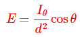
The equation combines the inverse-square term with the projected-area term for a point source.
Iθ is the source’s luminous intensity toward the receiving point, Ɵ is the angle between the plane normal and the ray from source to point, and d is the source-to-point distance.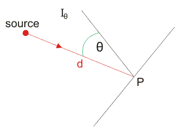
For an extended source, integrate the illuminance contributions from its visible elements or use suitable photometric data. Replacing intensity with total flux alone does not preserve directional information.
Illuminance is incident luminous flux per unit receiving area. Both source distance and receiving-plane orientation affect the direct component.
Illuminance reaches its maximum for a given I and d when the ray is normal to the receiving plane, so cos θ equals 1.
Tilting the same physical area reduces its projected area perpendicular to the ray. The area therefore intercepts less of the incident beam.
- For the same physical area δA, tilting by θ reduces the intercepted flux by the projection factor cos θ.
- If the same luminous flux is spread over a larger area δA, the illuminance
 falls. Increasing area does not by itself guarantee that flux stays constant.
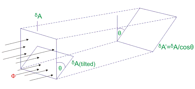
For case (1), when element δA is tilted by angle Ɵ, the intercepted flux is:
The received flux is reduced by the factor cos Ɵ.
The illuminance on δA is therefore:
For case (2), suppose the same intercepted flux is distributed over the larger element δA’:
The resulting illuminance is:
Both geometric approaches give: