
- Block Diagram Definition: A block diagram is defined as a diagram that represents each element of a control system with a block, symbolizing the transfer function of that element.
- Transfer Functions: Each block’s transfer function represents the relationship between the input and output of that specific control element.
- Block Diagram Reduction: This is the process of simplifying complex control system diagrams by combining individual blocks according to set rules.
- Summing Points: These points combine multiple input signals into one, influencing the control system’s overall input.
- How To Read Control System Block Diagrams: To read a control system block diagram, follow the signal flow through interconnected blocks, noting how take-off points and summing points affect the system.
What is a Block Diagram in a Control System?
A block diagram shows each element of a control system as a box that holds that element’s transfer function. Read the diagram by following the signal from the reference input through those boxes to the output.
The overall transfer function of that diagram is C(s)/R(s): the Laplace transform of the output divided by the Laplace transform of the input, with zero initial conditions. A large diagram is reduced to that single ratio by combining blocks, summing points and take-off points.
Each block holds one element’s transfer function and sits on the signal flow path from input to output.
Those connected blocks are the working model of the plant, the controller and any feedback path.
The figure below shows two elements with transfer function Gone(s) and Gtwo(s). Gone(s) belongs to the first element and Gtwo(s) belongs to the second.
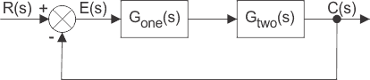
The diagram also shows a feedback path that returns the output C(s) so it can be compared with the input R(s). The difference between input and output is the actuating signal, also called the error signal.
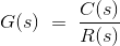

In each block, the output and input are tied by that block’s transfer function. That transfer function is:
C(s) is the output of that block and R(s) is its input.
A complex control system uses several such blocks. The overall transfer function is C(s)/R(s), the ratio of the final output transform to the initial input transform.
This system’s overall transfer function is obtained by combining those blocks one at a time until a single C(s)/R(s) remains.
The method of combining the blocks is the block diagram reduction technique.
For the reduction to stay equivalent to the original diagram, follow the block-diagram algebra rules below.
The rules below reduce a control system block diagram to a single transfer function. Practice items are in the control systems MCQs.
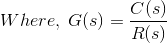
If the transfer function of input of control system is R(s) and the corresponding output is C(s), and the overall transfer function of the control system is G(s), then the control system can be represented as:
Take off Point in a Control System Block Diagram
A signal that must enter more than one block is copied at a take-off point.
From that point every connected path carries the original signal at full value.
Each path therefore carries the original signal, with no change of magnitude from the branching itself.
Use a take-off point whenever one measured signal must feed two or more blocks.
The figure below marks that common point as X.

Cascade Blocks
When control blocks are connected in series (cascaded), the overall transfer function is the product of the individual block transfer functions.
That product holds when each block is unilateral: a later block does not load the output of an earlier block.

From the diagram,
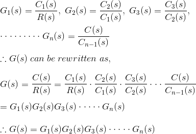
G(s) is then the overall transfer function of the cascaded chain.

Summing Points in a Control System Block Diagram
A block can also receive several signals at once, instead of one signal being copied to several blocks.
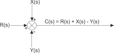
The combined input is the algebraic sum of those signals. The merge is drawn as a crossed circle.
R(s), X(s) and Y(s) are the input signals. Mark the plus or minus sign on each arrow that enters a summing point in the control system’s block diagram.
Consecutive Summing Points
A summing point with more than two inputs can be split into consecutive summing points. Swapping the order of those consecutive summing points does not change the output signal.
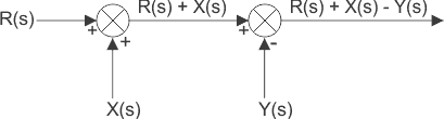
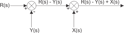
If two summing points sit next to each other, they may be swapped without changing the summed result.
Parallel Blocks
When the same input is applied to several blocks, their outputs are added at a summing point to form the system output.
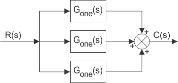
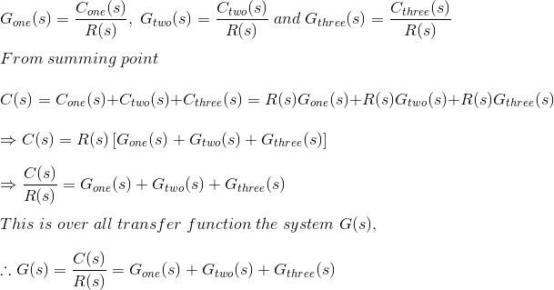

The overall transfer function is the algebraic sum of the individual block transfer functions.
If Cone, Ctwo and Cthree are the outputs of blocks Gone, Gtwo and Gthree, then
Shifting of Takeoff Point
If the same signal must reach more than one system, that branch is drawn from a take-off point.
The rule for shifting the take-off point is that it may move to either side of a block only if every branch leaving that point still carries the same signal as before.

The take-off point can move to either side of the block.
In the figure above, the take-off point moves from A to B. The signal R(s) at A becomes G(s)R(s) at B.

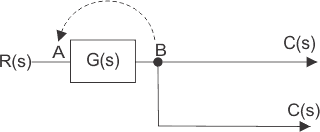

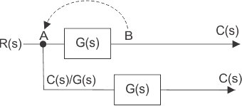

Hence another block of transfer function 1/G(s) is placed on that path so the branch again equals R(s).
Now move the take-off point to a position before the block when it first sat after the block.
Here the output is C(s) and the input is R(s).
Place one block of transfer function G(s) on the branch so the branch output is again C(s).
Shifting of Summing Point
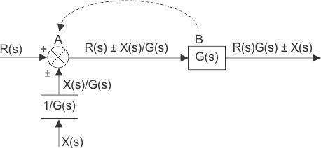
Now shift a summing point from a position before a block to a position after that block.
Two input signals, R(s) and ± X(s), enter a summing point at position A. The output of that summing point is R(s) ± X(s).
That result is the input to a block of transfer function G(s), so the final output of the system is


Hence the summing point can be redrawn with input signals R(s)G(s) and ± X(s)G(s)


The output of those block diagrams can be rewritten as

That equation is a block of transfer function G(s) whose input is R(s) ± X(s)/G(s). The term R(s)±X(s)/G(s) is itself a summing point with inputs R(s) and ± X(s)/G(s), drawn as below.
Block Diagram of Closed Loop Control System
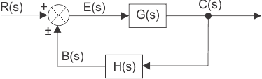
In a closed-loop control system, a fraction of the output is fed back and compared with the reference input at the summing point. If H(s) is the transfer function of the feedback path, the feedback signal is B(s) = C(s)H(s).
At the summing point, R(s) is combined with B(s) using the marked sign. For negative feedback the actuating error is E(s) = R(s) – B(s).





