- Insulator Types Definition: There are five main types of insulators used in transmission lines: Pin, Suspension, Strain, Stay, and Shackle.
- Pin Insulator Application: Pin insulators are used in systems up to 33 kV and come in different parts depending on the voltage.
- Suspension Insulator Advantages: Suspension insulators are used for high voltages and consist of disc insulators connected in series.
- Strain Insulator Function: Strain insulators handle significant tensile loads in areas like dead ends or sharp corners of transmission lines.
- Stay and Shackle Insulators: Stay insulators prevent guy-wires from falling in low voltage lines, and shackle insulators are used in low voltage distribution networks.
Type of Insulators Used in Transmission lines
The frozen list names 5 types of insulators used on overhead lines. It is a simplified functional classification, not a complete product standard.
- Pin Insulator
- Suspension Insulator
- Strain Insulator
- Stay Insulator
- Shackle Insulator
Pin and shackle designs are common on distribution circuits. Suspension, tension and line-post designs cover a broad range of voltage levels. The selected type must meet the line’s electrical load, mechanical load, pollution exposure and construction standard.
Pin Insulator
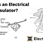
Pin insulators support a conductor above a threaded or cemented pin on the crossarm. These overhead insulators are used mainly on distribution lines. One-piece and multi-piece ceramic designs exist, but their application is set by product ratings and utility standards rather than one universal voltage limit.
A utility may use a one-piece pin insulator on an 11 kV circuit when its wet and dry withstand, mechanical strength and creepage distance meet the project specification.
The creepage path of an insulator follows its surface between conductive parts. Sheds increase that surface distance within a compact height. The required creepage distance and shed profile depend on contamination, wetting, material behaviour and system stress.
Sheds also shield part of the surface from direct rain and change how water and contamination form a conductive layer. Their underside is not guaranteed to remain dry or non-conductive. Wet flashover performance is verified by standard tests on the complete insulator.

As required withstand voltage and creepage distance increase, a pin-type ceramic body becomes larger and harder to manufacture without defects. Line-post or suspension arrangements are often more practical for higher-voltage duties. The transition is a design choice, not a fixed 33 kV or 66 kV boundary.
A traditional multi-piece pin insulator joins shaped porcelain shells into one unit with cement. The number of shells does not by itself define the system voltage. The finished unit must carry a specified rating and pass the applicable mechanical and electrical tests.
Designing Consideration of Electrical Insulator
The live conductor sits in the top groove while the pin connects the lower part to the support. The insulator must withstand the specified electrical stress between the conductor and earthed hardware. The shortest air path between energised and earthed metal parts is the arcing distance. Flashover voltage is a tested electrical characteristic, not simply that distance.
- When the insulator is wet, its outer surface becomes almost conducting. Hence the flashover distance of insulator is decreased. The design of an electrical insulator should be such that the decrease of flashover distance is minimum when the insulator is wet. That is why the uppermost petticoat of a pin insulator has umbrella type designed so that it can protect, the rest lower part of the insulator from the rain. The upper surface of the topmost petticoat is inclined as less as possible to maintain maximum flashover voltage during raining.
- The rain sheds are made in such a way that they should not disturb the voltage distribution. They are so designed that their subsurface at a right angle to the electromagnetic lines of force.
Post Insulator
Post insulators are rigid members that support conductors or equipment while resisting bending and compression. Line-post and station-post products have different applications and standards.
Post insulators can be mounted vertically or horizontally when rated for that loading direction. Ceramic, glass and composite designs exist. Metal fittings at the line and support ends transfer the mechanical loads. Shed count and height follow the required electrical performance rather than a fixed comparison with pin units.

The frozen table gives a historical comparison. Current pin and post products vary in material, construction, voltage range and mounting hardware, so project specifications take precedence.
| SL | Pin Insulator | Post Insulator |
| 1 | It is generally used up to 33KV system | It is suitable for lower voltage and also for higher voltage |
| 2 | It is single stag | It can be single stag as well as multiple stags |
| 3 | Conductor is fixed on the top of the insulator by binding | Conductor is fixed on the top of the insulator with help of connector clamp |
| 4 | Two insulators cannot be fixed together for higher voltage application | Two or more insulators can be fixed together one above other for higher voltage application |
| 4 | Metallic fixing arrangement provided only on bottom end of the insulator | Metallic fixing arrangement provided on both top and bottom ends of the insulator |
Suspension Insulator

A suspension insulator hangs the conductor below the support from a flexible string or long-rod unit. Suspension construction is common when electrical clearances and mechanical loads make a rigid pin arrangement unsuitable. The economic transition is project-specific rather than fixed at 33 kV.
A cap-and-pin suspension insulator string connects several units in series, with the conductor attached at the line end. Ceramic or toughened-glass units often have a disc shape. Composite long-rod suspension insulators can provide the same mechanical function without separate discs.
Advantages of Suspension Insulator
- Each suspension disc is designed for normal voltage rating 11KV (Higher voltage rating 15KV), so by using different numbers of discs, a suspension string can be made suitable for any voltage level.
- If any one of the disc insulators in a suspension string is damaged, it can be replaced much easily.
- Mechanical stresses on the suspension insulator is less since the line hanged on a flexible suspension string.
- As the current carrying conductors are suspended from supporting structure by suspension string, the height of the conductor position is always less than the total height of the supporting structure. Therefore, the conductors may be safe from lightening.

Disadvantages of Suspension Insulator
- Suspension insulator string costlier than pin and post type insulator.
- Suspension string requires more height of supporting structure than that for pin or post insulator to maintain same ground clearance of current conductor.
- The amplitude of free swing of conductors is larger in suspension insulator system, hence, more spacing between conductors should be provided.
Strain Insulator

A strain insulator is a suspension or long-rod assembly installed in tension at a dead end, a large line angle or another point where the transmission line applies longitudinal load. A strain insulator must meet its specified mechanical load as well as its electrical withstand. The frozen table gives example disc counts only; insulation coordination and unit ratings determine the actual string.
| Rated System Voltage | Number of disc insulator used in strain type tension insulator string | Number of disc insulator used in suspension insulator string |
| 33KV | 3 | 3 |
| 66KV | 5 | 4 |
| 132KV | 9 | 8 |
| 220KV | 15 | 14 |
Stay Insulator

A guy or stay wire may use a stay insulator to isolate its lower section from the support. The arrangement limits the length of guy wire that could become energised if it contacts a conductor. Its position, mechanical rating and grounding must follow the applicable line-construction rules.

Shackle Insulator
A shackle insulator, also called a spool insulator, supports a conductor on some low-voltage overhead distribution structures. Depending on its design and load rating, it can be mounted horizontally or vertically. Use varies by utility construction standard.
The central hole and groove of a spool insulator transfer load through its mounting hardware. A conductor may be secured in the groove with an approved tie wire or clamp. The complete shackle insulator assembly must stay within its mechanical and electrical ratings.