

- Tan Delta Test Definition: Tan delta is defined as the ratio of the resistive to capacitive components of electrical leakage current, indicating insulation health.
- Insulator Functionality: An ideal insulator behaves like a capacitor with no impurities, purely allowing capacitive current flow.
- Importance of Testing: Testing insulation with the tan delta test at low frequencies ensures accurate assessment of insulation health by controlling power requirements and improving measurement precision.
- Analyzing Results: Tan delta values provide insights into the insulation’s condition; stable values across different voltages suggest good insulation, while increasing values indicate deterioration.
- Equipment Maintenance: Based on tan delta results, decisions can be made regarding the maintenance or replacement of electrical equipment to prevent failures.
Principle of Tan Delta Test
An electrical insulator between an energised conductor and earth can be represented by a capacitor with a parallel loss path. An ideal loss-free dielectric would carry only capacitive electric current. Real insulation also carries a smaller in-phase loss current.
For an ideal capacitor, current leads the applied voltage by 90o.
In real insulation, conduction and dielectric polarisation produce loss. Moisture, contamination, ageing products, temperature and physical damage can change the measured loss, but the result also depends on the material and test frequency.
In the simplified parallel model, dissipation factor is tan δ = I_R/I_C. A lower value usually indicates lower dielectric loss under the same test conditions. It does not by itself prove that an insulation system is defect-free.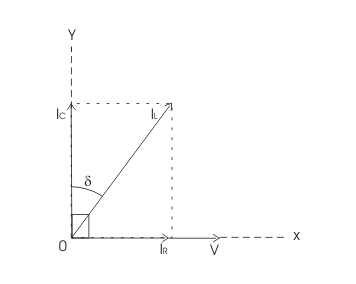
In the vector diagram, voltage is on the x-axis. The in-phase loss-current component IR is also on that axis.
The capacitive component IC leads voltage by 90o and lies on the y-axis.
The total current IL combines Ic and IR as vectors. Its displacement from the capacitive axis is δ.
The geometry gives tan δ = IR/IC for this equivalent circuit.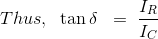
NB: The angle δ is the dielectric loss angle.
Method of Tan Delta Testing
A cable, winding, current transformer, potential transformer or bushing must be isolated, discharged and connected according to the approved procedure before a tan delta test or dissipation factor test. The test frequency and connection depend on the asset and diagnostic method.
The instrument applies a specified AC test voltage and measures voltage, current, phase angle, capacitance and loss. A voltage tip-up test repeats measurements at approved voltage steps to identify voltage dependence. The test voltage must come from the applicable standard or manufacturer procedure, not a universal multiple of normal voltage. Results are compared only after accounting for test conditions and the tan delta method used.
Very-low-frequency excitation is used for some cable tests, while other equipment is tested at 50/60 Hz, 1 Hz or across a frequency range.
Reason for Applying Very Low Frequency
For a mainly capacitive cable, capacitive reactance decreases as frequency rises. Testing a long cable at power frequency can therefore require a large current and a high-rated source.
Using VLF can reduce the source rating for a cable tan delta test. IEEE 400.2 covers field testing of shielded power-cable systems below 1 Hz. That scope does not make VLF mandatory for every dissipation factor test, and the selected waveform and frequency must match the procedure.
Lower frequencies can also increase sensitivity to moisture or conductive contamination in some insulation systems. This sensitivity is a diagnostic property, not a universal rule that lower is always better.
For a simplified parallel model,
tan δ can be written as G/(2πfC) only when conductance G and capacitance C are treated as fixed.
Real dielectric properties vary with frequency and temperature, so tan δ is not universally proportional to 1/f. Frequency-response testing uses that variation as diagnostic information.
How to Predict the Result of Tan Delta Testing
A tan delta result is interpreted with asset-specific limits, test conditions and comparison data. No single number describes every insulation system.
Historical trending compares like-for-like results at the same frequency, voltage, temperature and test connection. A consistent change can indicate ageing, moisture, contamination or another developing condition.
When no baseline exists, compare phases or similar units and use limits from the equipment manufacturer or applicable guide. Capacitance, temperature, voltage dependence and other diagnostic tests can provide needed context.
Voltage dependence, often called tan-delta tip-up, can indicate local defects or nonlinear loss mechanisms in some assets. A flat response is not proof of perfect insulation, and an increasing response needs asset-specific investigation.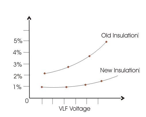
The illustrated curve shows one possible increase with test voltage. Maintenance decisions should combine tan&delta trend, capacitance, temperature, frequency, phase comparison and other evidence rather than using this curve as a universal replacement rule.


Very good &easily understandable article. Thanks for sharing
No worries Venkat – thank you for your kind words.
Very useful and easily understandable article.
Thank you Amit – very happy to hear!
Very good and very clearly explained article.Thanks for sharing.
No worries at all Kaishnair. Happy to hear you found the information helpful!